ESP32-2432S028 ESP32-2432S024 JC2432W328 ESP32-2432S032C
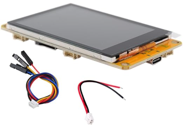
For those who want to build a project using the ESP32 and an integrated 320×240 pixel screen, there is a range of very interesting boards available. They come with either…
For those who want to build a project using the ESP32 and an integrated 320×240 pixel screen, there is a range of very interesting boards available. They come with either…