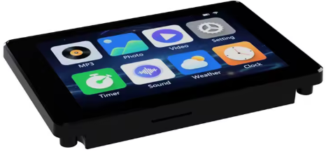
Le module JC3248W535 (référence exacte : JC3248W535C_I_Y) est une excellente solution basée sur le puissant microcontrôleur ESP32-S3. Il intègre un écran tactile capacitif, une interface pour carte SD et plusieurs GPIO accessibles. On le trouve sur AliExpress à un prix raisonnable.
Caractéristiques principales
- Écran LCD-TFT tactile capacitif de 3,5 pouces avec boîtier.
- Support WiFi et Bluetooth.
- Alimentation par batterie lithium possible.
- Résolution de 320 * 480 pixels.
- Dalle en verre IPS, couleurs RGB 65K.
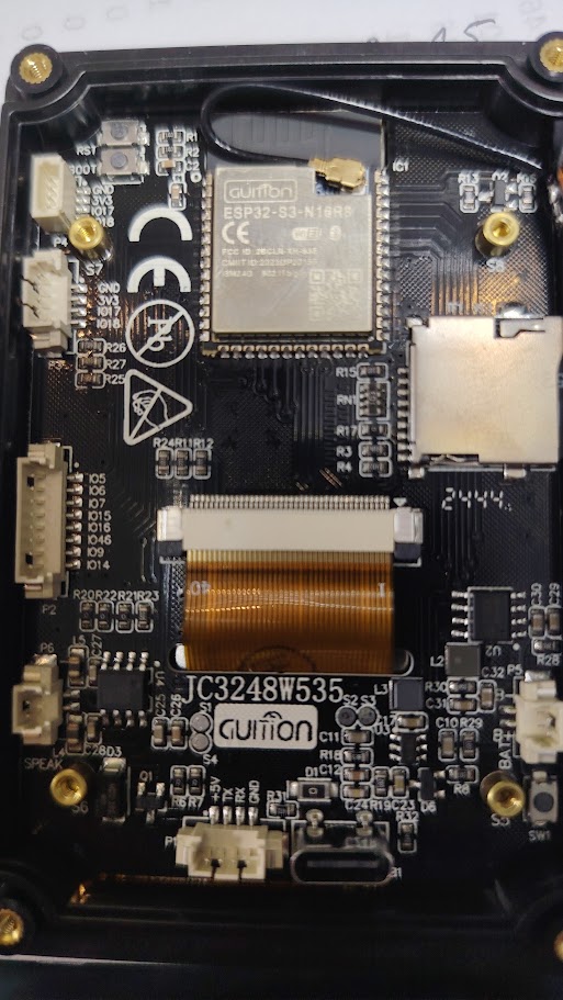
- Contrôleur ESP32-S3 N16R8 (CPU double cœur, 240 MHz).
- Mémoire : 8 Mo de PSRAM et 16 Mo de FLASH.
- Sortie audio I2S pour haut-parleur.
Exemple de code – Affichage et Tactile – Arduino IDE
Exemple de code – Affichage et Tactile – Arduino IDE
Le code fourni sur la page est un programme simple pour démontrer l’utilisation du module.
Note : Ce code n’utilise pas de bibliothèques complexes comme LVGL.
Bibliothèque requise : ArduinoGFX.
/*
* Exemple fourni par F1ATB
*
*/
#include <Arduino_GFX_Library.h>
#include <Wire.h>

// Pin definitions
#define GFX_BL 1
#define TOUCH_ADDR 0x3B
#define TOUCH_SDA 4
#define TOUCH_SCL 8
#define TOUCH_I2C_CLOCK 400000
#define TOUCH_RST_PIN 12
#define TOUCH_INT_PIN 11
#define AXS_MAX_TOUCH_NUMBER 1

Arduino_DataBus *bus = new Arduino_ESP32QSPI(45, 47, 21, 48, 40, 39);
Arduino_GFX *g = new Arduino_AXS15231B(bus, GFX_NOT_DEFINED, 0, false, 320, 480);
Arduino_Canvas *gfx = new Arduino_Canvas(320, 480, g, 0, 0, 0);

uint16_t touchX, touchY;

void setup() {
  Serial.begin(115200);

  // Initialize Display
  gfx->begin();

  // Initialize touch
  Wire.begin(TOUCH_SDA, TOUCH_SCL);
  Wire.setClock(TOUCH_I2C_CLOCK);

  // Configure touch pins
  pinMode(TOUCH_INT_PIN, INPUT_PULLUP);
  pinMode(TOUCH_RST_PIN, OUTPUT);
  digitalWrite(TOUCH_RST_PIN, LOW);
  delay(200);
  digitalWrite(TOUCH_RST_PIN, HIGH);
  delay(200);

  gfx->setRotation(1);
  gfx->fillScreen(RGB565_BLUE);
  pinMode(GFX_BL, OUTPUT);  //Back Light On
  digitalWrite(GFX_BL, HIGH);
  gfx->setTextSize(2);
  gfx->setTextColor(RGB565_GREEN);
  gfx->setCursor(150, 10);
  gfx->print("Hello from F1ATB");
  gfx->setCursor(180, 100);
  gfx->print("Touch Screen");
  gfx->flush();
}

void loop() {
  if (getTouchPoint(touchX, touchY)){
    Serial.println("Touch Pressed:" + String(touchX) + "," + String(touchY));
    gfx->fillRect(180, 100, 200, 20, RGB565_BLUE);
    gfx->setCursor(200, 100);
    gfx->print(String(touchX) + "," + String(touchY));
    gfx->drawCircle(touchX, touchY, 2, RGB565_WHITE);
    gfx->flush();
  }
  delay(5);
}

bool getTouchPoint(uint16_t &x, uint16_t &y) {
    uint8_t data[AXS_MAX_TOUCH_NUMBER * 6 + 2] = {0};

    // Define the read command array properly
    const uint8_t read_cmd[11] = {
        0xb5, 0xab, 0xa5, 0x5a, 0x00, 0x00,
        (uint8_t)((AXS_MAX_TOUCH_NUMBER * 6 + 2) >> 8),
        (uint8_t)((AXS_MAX_TOUCH_NUMBER * 6 + 2) & 0xff),
        0x00, 0x00, 0x00
    };

    Wire.beginTransmission(TOUCH_ADDR);
    Wire.write(read_cmd, 11);
    if (Wire.endTransmission() != 0) return false;

    if (Wire.requestFrom(TOUCH_ADDR, sizeof(data)) != sizeof(data)) return false;

    for (int i = 0; i < sizeof(data); i++) {
        data[i] = Wire.read();
    }

    if (data[1] > 0 && data[1] <= AXS_MAX_TOUCH_NUMBER) {
        uint16_t rawX = ((data[2] & 0x0F) << 8) | data[3];
        uint16_t rawY = ((data[4] & 0x0F) << 8) | data[5];
        if (rawX > 500 || rawY > 500) return false;
        y = map(rawX, 0, 320, 320, 0);
        x = rawY;
        return true;
    }
    return false;
}
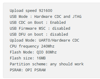
Paramètres de configuration (Arduino IDE) : Avant de compiler, sélectionnez le module ESP32S3 Dev Module et vérifiez les paramètres suivants :
USB CDC on Boot : Enabled (Activé), pour permettre l’affichage des données sur le moniteur série.
Exemple de code – Lecture/Écriture carte SD
Ce module utilise le brochage standard d’un ESP32-S3 pour le lecteur SD :
- CS : GPIO10
- MOSI : GPIO11
- SCLK : GPIO12
- MISO : GPIO13
L’exemple « SD_Test.ino » fourni avec l’IDE Arduino fonctionne directement sans modification.
The IDE Arduino example called SD_Test.ino is good solution to check the SD card reader. Just compile it, there is no need to adapt something.
Exemple de code – PlatformIO IDE
Si vous utilisez PlatformIO avec le framework Arduino, le code est quasiment identique.
/*
 * Exemple fourni par F1ATB
 *
 */
#include <Arduino_GFX_Library.h>
#include <Wire.h>

// Pin definitions
#define GFX_BL 1
#define TOUCH_ADDR 0x3B
#define TOUCH_SDA 4
#define TOUCH_SCL 8
#define TOUCH_I2C_CLOCK 400000
#define TOUCH_RST_PIN 12
#define TOUCH_INT_PIN 11
#define AXS_MAX_TOUCH_NUMBER 1

//************Alternative declarations *******************************************
// Arduino_DataBus *bus = new Arduino_ESP32QSPI(45, 47, 21, 48, 40, 39);
// Arduino_GFX *g = new Arduino_AXS15231B(bus, GFX_NOT_DEFINED, 0, false, 320, 480);
// Arduino_Canvas *gfx = new Arduino_Canvas(320, 480, g, 0, 0, 0);
//*******************************************************************************

Arduino_ESP32QSPI *bus = new Arduino_ESP32QSPI(45, 47, 21, 48, 40, 39);
Arduino_AXS15231B *g = new Arduino_AXS15231B(bus, GFX_NOT_DEFINED, 0, false, 320, 480);
Arduino_Canvas *gfx = new Arduino_Canvas(320, 480, g, 0, 0, 0);

uint16_t touchX, touchY;

// Prototypes
bool getTouchPoint(uint16_t &x, uint16_t &y);

void setup()
{
  Serial.begin(115200);

  // Initialize Display
  gfx->begin();

  // Initialize touch
  Wire.begin(TOUCH_SDA, TOUCH_SCL);
  Wire.setClock(TOUCH_I2C_CLOCK);

  // Configure touch pins
  pinMode(TOUCH_INT_PIN, INPUT_PULLUP);
  pinMode(TOUCH_RST_PIN, OUTPUT);
  digitalWrite(TOUCH_RST_PIN, LOW);
  delay(200);
  digitalWrite(TOUCH_RST_PIN, HIGH);
  delay(200);

  gfx->setRotation(1);
  gfx->fillScreen(RGB565_BLUE);
  pinMode(GFX_BL, OUTPUT); // Back Light On
  digitalWrite(GFX_BL, HIGH);
  gfx->setTextSize(2);
  gfx->setTextColor(RGB565_GREEN);
  gfx->setCursor(150, 10);
  gfx->print("Hello from F1ATB");
  gfx->setCursor(180, 100);
  gfx->print("Touch Screen");
  gfx->flush();
}

void loop()
{
  if (getTouchPoint(touchX, touchY))
  {
    Serial.println("Touch Pressed:" + String(touchX) + "," + String(touchY));
    gfx->fillRect(180, 100, 200, 20, RGB565_BLUE);
    gfx->setCursor(200, 100);
    gfx->print(String(touchX) + "," + String(touchY));
    gfx->drawCircle(touchX, touchY, 2, RGB565_WHITE);
    gfx->flush();
  }
  delay(5);
}

bool getTouchPoint(uint16_t &x, uint16_t &y)
{
  uint8_t data[AXS_MAX_TOUCH_NUMBER * 6 + 2] = {0};

  // Define the read command array properly
  const uint8_t read_cmd[11] = {
      0xb5, 0xab, 0xa5, 0x5a, 0x00, 0x00,
      (uint8_t)((AXS_MAX_TOUCH_NUMBER * 6 + 2) >> 8),
      (uint8_t)((AXS_MAX_TOUCH_NUMBER * 6 + 2) & 0xff),
      0x00, 0x00, 0x00};

  Wire.beginTransmission(TOUCH_ADDR);
  Wire.write(read_cmd, 11);
  if (Wire.endTransmission() != 0)
    return false;

  if (Wire.requestFrom(TOUCH_ADDR, sizeof(data)) != sizeof(data))
    return false;

  for (int i = 0; i < sizeof(data); i++)
  {
    data[i] = Wire.read();
  }

  if (data[1] > 0 && data[1] <= AXS_MAX_TOUCH_NUMBER)
  {
    uint16_t rawX = ((data[2] & 0x0F) << 8) | data[3];
    uint16_t rawY = ((data[4] & 0x0F) << 8) | data[5];
    if (rawX > 500 || rawY > 500)
      return false;
    y = map(rawX, 0, 320, 320, 0);
    x = rawY;
    return true;
  }
  return false;
}
Partitionnement : L’auteur propose un fichier de partition pour exploiter les 16 Mo de Flash :
Capacité OTA (mise à jour sans fil) incluse.
6,5 Mo pour l’application (app0).
6,5 Mo pour la mise à jour (app1).
2 Mo pour le stockage (SPIFFS ou LittleFS).
# Name,   Type, SubType, Offset,  Size,      Flags
nvs,      data, nvs,     0x9000,  0x5000,
otadata,  data, ota,     0xe000,  0x2000,
app0,     app,  ota_0,   0x10000, 0x660000,
app1,     app,  ota_1,   0x670000,0x660000,
spiffs,   data, spiffs,  0xCD0000,0x200000,
corredump,data,coredump,     ,64K,
Vous pouvez télécharger ici le code complet.
Matériel et Connectique (Hardware)
Pinout
Alimentation et Programmation : Via USB-C ou un connecteur 4 broches JST1.25 (Gnd, TX, RX, +5V).
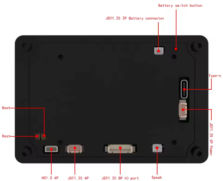
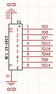
Un connecteur JST1.25 permet d’acceder à différents GPIO pour y connecter des éléments externes.
GPIO Externes : Un connecteur JST1.25 offre 8 broches GPIO.
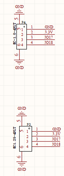
Capteurs : Deux connecteurs 4 broches (HC1.0 et JST1.25) fournissent GND, 3.3V, GPIO17 et GPIO18.
Audio : Un haut-parleur peut être branché sur un connecteur 2 broches JST1.25.
Liste d’achats
Principalement sur Aliexpress