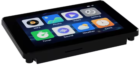
The module JC3248W535 ( JC3248W535C_I_Y ) offers a great solution based on a powerful ESP32-S3 microcontroller, a capacitive touch display, an SD card interface and various accessible GPIOs. You can buy it on Aliexpress at a reasonable price.
Main characteristics
- 3.5-inch LCD-TFT capacitive touch display module with housing
- Supports WiFi and Bluetooth
- Support lithium battery power supply
- Capacitive touch
- 320 * 480 screen resolution
- RGB 65K colors
- IPS glass panel
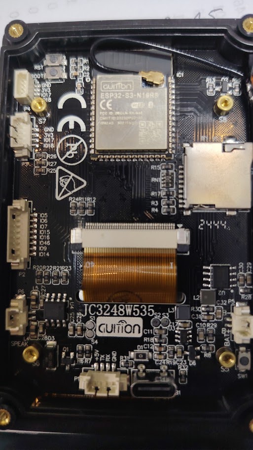
- ESP32-S3 N16R8 controller dual core CPU
- Clock frequency 240MHz
- 8M PSRAM
- 16M FLASH
- I2S Audio
- Speaker output
Code sample – Display and Touch screen – Arduino IDE
The following code is a simple program to demonstrate how to use the module and compile it on Arduino IDE. ArduinoGFX is the graphic library to be installed. It does not use libraries as LVGL.
/*
* Example provided by F1ATB
*
*/
#include <Arduino_GFX_Library.h>
#include <Wire.h>

// Pin definitions
#define GFX_BL 1
#define TOUCH_ADDR 0x3B
#define TOUCH_SDA 4
#define TOUCH_SCL 8
#define TOUCH_I2C_CLOCK 400000
#define TOUCH_RST_PIN 12
#define TOUCH_INT_PIN 11
#define AXS_MAX_TOUCH_NUMBER 1

Arduino_DataBus *bus = new Arduino_ESP32QSPI(45, 47, 21, 48, 40, 39);
Arduino_GFX *g = new Arduino_AXS15231B(bus, GFX_NOT_DEFINED, 0, false, 320, 480);
Arduino_Canvas *gfx = new Arduino_Canvas(320, 480, g, 0, 0, 0);

uint16_t touchX, touchY;

void setup() {
  Serial.begin(115200);

  // Initialize Display
  gfx->begin();

  // Initialize touch
  Wire.begin(TOUCH_SDA, TOUCH_SCL);
  Wire.setClock(TOUCH_I2C_CLOCK);

  // Configure touch pins
  pinMode(TOUCH_INT_PIN, INPUT_PULLUP);
  pinMode(TOUCH_RST_PIN, OUTPUT);
  digitalWrite(TOUCH_RST_PIN, LOW);
  delay(200);
  digitalWrite(TOUCH_RST_PIN, HIGH);
  delay(200);

  gfx->setRotation(1);
  gfx->fillScreen(RGB565_BLUE);
  pinMode(GFX_BL, OUTPUT);  //Back Light On
  digitalWrite(GFX_BL, HIGH);
  gfx->setTextSize(2);
  gfx->setTextColor(RGB565_GREEN);
  gfx->setCursor(150, 10);
  gfx->print("Hello from F1ATB");
  gfx->setCursor(180, 100);
  gfx->print("Touch Screen");
  gfx->flush();
}

void loop() {
  if (getTouchPoint(touchX, touchY)){
    Serial.println("Touch Pressed:" + String(touchX) + "," + String(touchY));
    gfx->fillRect(180, 100, 200, 20, RGB565_BLUE);
    gfx->setCursor(200, 100);
    gfx->print(String(touchX) + "," + String(touchY));
    gfx->drawCircle(touchX, touchY, 2, RGB565_WHITE);
    gfx->flush();
  }
  delay(5);
}

bool getTouchPoint(uint16_t &x, uint16_t &y) {
    uint8_t data[AXS_MAX_TOUCH_NUMBER * 6 + 2] = {0};

    // Define the read command array properly
    const uint8_t read_cmd[11] = {
        0xb5, 0xab, 0xa5, 0x5a, 0x00, 0x00,
        (uint8_t)((AXS_MAX_TOUCH_NUMBER * 6 + 2) >> 8),
        (uint8_t)((AXS_MAX_TOUCH_NUMBER * 6 + 2) & 0xff),
        0x00, 0x00, 0x00
    };

    Wire.beginTransmission(TOUCH_ADDR);
    Wire.write(read_cmd, 11);
    if (Wire.endTransmission() != 0) return false;

    if (Wire.requestFrom(TOUCH_ADDR, sizeof(data)) != sizeof(data)) return false;

    for (int i = 0; i < sizeof(data); i++) {
        data[i] = Wire.read();
    }

    if (data[1] > 0 && data[1] <= AXS_MAX_TOUCH_NUMBER) {
        uint16_t rawX = ((data[2] & 0x0F) << 8) | data[3];
        uint16_t rawY = ((data[4] & 0x0F) << 8) | data[5];
        if (rawX > 500 || rawY > 500) return false;
        y = map(rawX, 0, 320, 320, 0);
        x = rawY;
        return true;
    }
    return false;
}
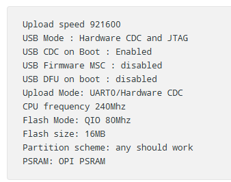
Before compiling, select the ESP32S3 Dev Module and verify the following parameters. In particular, USB CDC on Boot : Enabled, to allow data published on the serial interface.
Code example – SD card read and write
This module uses the standard interface pinout of an ESP2-S3 :
- CS : GPIO10
- MOSI : GPIO11
- SCLK : GPIO12
- MISO : GPIO13
The IDE Arduino example called SD_Test.ino is good solution to check the SD card reader. Just compile it, there is no need to adapt something.
Code sample – Display and Touch screen – PlatformIO IDE – Arduino Framework
If you compile on PlatformIO IDE with the Arduino Framwork , the code is very similar. In main.cpp you have :
/*
 * Sample provided by F1ATB
 *
 */
#include <Arduino_GFX_Library.h> //Works with Version 1.6.0 and not 1.6.1 (October 2025)
#include <Wire.h>

// Pin definitions
#define GFX_BL 1
#define TOUCH_ADDR 0x3B
#define TOUCH_SDA 4
#define TOUCH_SCL 8
#define TOUCH_I2C_CLOCK 400000
#define TOUCH_RST_PIN 12
#define TOUCH_INT_PIN 11
#define AXS_MAX_TOUCH_NUMBER 1

//************Alternative declarations *******************************************
// Arduino_DataBus *bus = new Arduino_ESP32QSPI(45, 47, 21, 48, 40, 39);
// Arduino_GFX *g = new Arduino_AXS15231B(bus, GFX_NOT_DEFINED, 0, false, 320, 480);
// Arduino_Canvas *gfx = new Arduino_Canvas(320, 480, g, 0, 0, 0);
//*******************************************************************************

Arduino_ESP32QSPI *bus = new Arduino_ESP32QSPI(45, 47, 21, 48, 40, 39);
Arduino_AXS15231B *g = new Arduino_AXS15231B(bus, GFX_NOT_DEFINED, 0, false, 320, 480);
Arduino_Canvas *gfx = new Arduino_Canvas(320, 480, g, 0, 0, 0);

uint16_t touchX, touchY;

// Prototypes
bool getTouchPoint(uint16_t &x, uint16_t &y);

void setup()
{
  Serial.begin(115200);

  // Initialize Display
  gfx->begin();

  // Initialize touch
  Wire.begin(TOUCH_SDA, TOUCH_SCL);
  Wire.setClock(TOUCH_I2C_CLOCK);

  // Configure touch pins
  pinMode(TOUCH_INT_PIN, INPUT_PULLUP);
  pinMode(TOUCH_RST_PIN, OUTPUT);
  digitalWrite(TOUCH_RST_PIN, LOW);
  delay(200);
  digitalWrite(TOUCH_RST_PIN, HIGH);
  delay(200);

  gfx->setRotation(1);
  gfx->fillScreen(RGB565_BLUE);
  pinMode(GFX_BL, OUTPUT); // Back Light On
  digitalWrite(GFX_BL, HIGH);
  gfx->setTextSize(2);
  gfx->setTextColor(RGB565_GREEN);
  gfx->setCursor(150, 10);
  gfx->print("Hello from F1ATB");
  gfx->setCursor(180, 100);
  gfx->print("Touch Screen");
  gfx->flush();
}

void loop()
{
  if (getTouchPoint(touchX, touchY))
  {
    Serial.println("Touch Pressed:" + String(touchX) + "," + String(touchY));
    gfx->fillRect(180, 100, 200, 20, RGB565_BLUE);
    gfx->setCursor(200, 100);
    gfx->print(String(touchX) + "," + String(touchY));
    gfx->drawCircle(touchX, touchY, 2, RGB565_WHITE);
    gfx->flush();
  }
  delay(5);
}

bool getTouchPoint(uint16_t &x, uint16_t &y)
{
  uint8_t data[AXS_MAX_TOUCH_NUMBER * 6 + 2] = {0};

  // Define the read command array properly
  const uint8_t read_cmd[11] = {
      0xb5, 0xab, 0xa5, 0x5a, 0x00, 0x00,
      (uint8_t)((AXS_MAX_TOUCH_NUMBER * 6 + 2) >> 8),
      (uint8_t)((AXS_MAX_TOUCH_NUMBER * 6 + 2) & 0xff),
      0x00, 0x00, 0x00};

  Wire.beginTransmission(TOUCH_ADDR);
  Wire.write(read_cmd, 11);
  if (Wire.endTransmission() != 0)
    return false;

  if (Wire.requestFrom(TOUCH_ADDR, sizeof(data)) != sizeof(data))
    return false;

  for (int i = 0; i < sizeof(data); i++)
  {
    data[i] = Wire.read();
  }

  if (data[1] > 0 && data[1] <= AXS_MAX_TOUCH_NUMBER)
  {
    uint16_t rawX = ((data[2] & 0x0F) << 8) | data[3];
    uint16_t rawY = ((data[4] & 0x0F) << 8) | data[5];
    if (rawX > 500 || rawY > 500)
      return false;
    y = map(rawX, 0, 320, 320, 0);
    x = rawY;
    return true;
  }
  return false;
}
I propose also a partition file within the 16MB of the Flash offering :
– 6.5MB for app0 ,
– 6.5MB for app1,
– 2MB for spiffs or little FS storage
and an OTA capability.
# Name,   Type, SubType, Offset,  Size,      Flags
nvs,      data, nvs,     0x9000,  0x5000,
otadata,  data, ota,     0xe000,  0x2000,
app0,     app,  ota_0,   0x10000, 0x660000,
app1,     app,  ota_1,   0x670000,0x660000,
spiffs,   data, spiffs,  0xCD0000,0x200000,
corredump,data,coredump,     ,64K,
You can download here the complete directory of the project including the platformio.ini file.
Hardware
Pinout
Power supply and data/program transfer can be provided via an USB-C or a 4pins (JST1.25) connector .(Gnd,TX,RX,+5V)
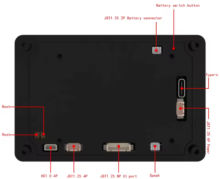
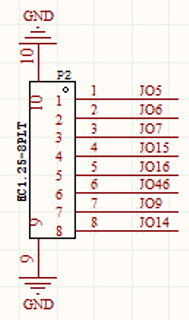
One connector JST1.25 provides 8 GPIOs to connect external devices
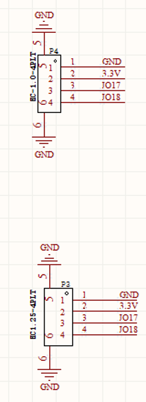
Two 4 pins connectors (HC1.0 and JST1.25) provide the same signals GND, 3.3V, GPIO17, GPIO18
A speaker can be connected on a 2 pins connector ( JST1.25)
Shopping List
Mainly on Aliexpress
- JC3248W535 (exact reference : JC3248W535C_I_Y )
- JST 1.25 connectors
- Power supply 5V 1A to USB-C