VHF or UHF NBFM Transceiver
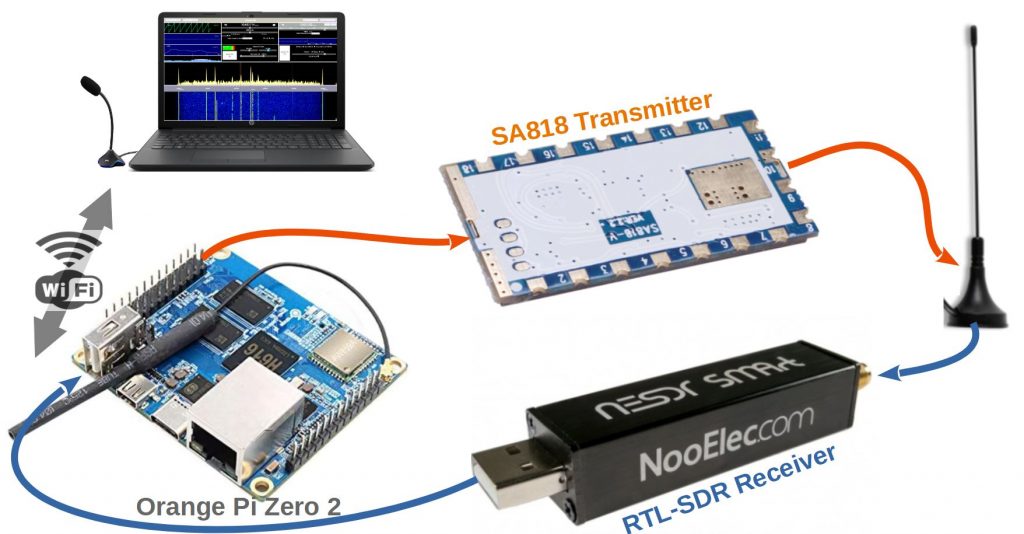
RTL-SDR is a low cost receiver solution, covering VHF / UHF and using SDR (software defined radio) technology. SA818 is also a low cost NBFM transceiver solution. Why not combine the 2 to create a transmitter / receiver similar to an SDR managed by a nanocomputer or SBC (Single Board Computer). Viewing and listening is done remotely via a web browser on PC, tablet or smartphone via “Remote SDR” application.
Note the existence of a similar project dealing with both VHF and UHF bands.
Characteristics
Receiver
- Hardware: RTL-SDR (example: NESDR SMArt from Nooelec)
- Frequency: VHF amateur band of 2 m or UHF band of 70 cm
- Spectral band processed: 2 MHz
- Audio: 1 channel
- Demodulation: NBFM, WBFM, AM and SSB
Transmitter
- Material: SA818 from G-NiceRF (Aliexpress)
- Frequency: VHF amateur band of 2 m or UHF band of 70 cm
- Power: 1W
- Audio: 1 channel
- Modulation: NBFM
Processing
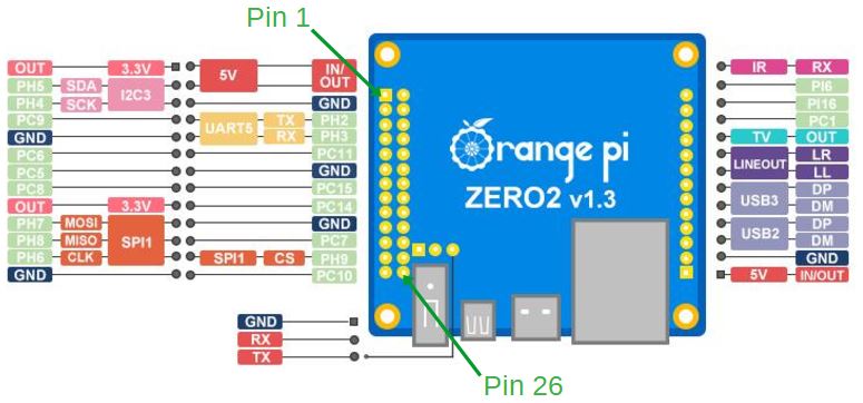
- Material: Orange Pi Zero 2
- Software: Remote SDR (version v3 minimum)
- Connection: wired Ethernet or WIFI
- Display and Audio: WEB page on PC, tablet or smartphone
Construction
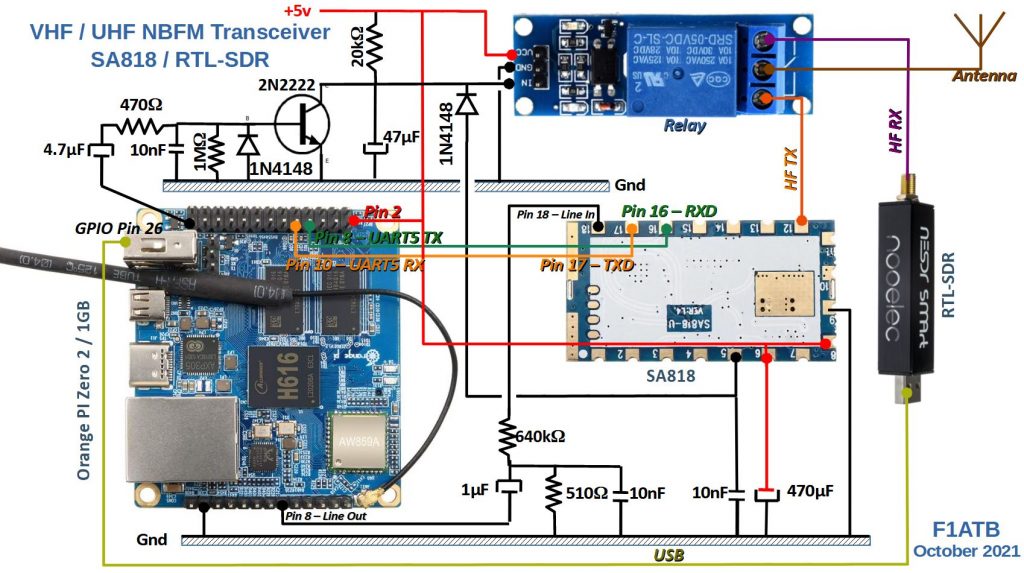
Receiver diagram
The antenna signal passes through a relay to reach the RTL-SDR receiver. Different models exist on the market, that of Nooelec is more stable on the quartz side, with a TCXO allowing to have a good accuracy and stability in frequency. It remains a simple SDR encoding the signals on 8 bits, which limits the dynamics of the processed signals. But it is sufficient for a simple transceiver. It can digitize a 2 MHz wideband, which is perfect for covering the entire 2 m band with one eye. The output is via the USB directly connected to the Orange Pi Zero 2 which is responsible for processing the signal.
Transmitter diagram
For this project, only the transmit part of a G-NiceRF SA818 module is used. It is available in 2 versions, SA818-V to cover VHF and SA818-U to cover UHF. For less than 20 €, you can buy a minimum of 2 from Aliexpress.
The SA818 is connected to the Orange Pi Zero 2 which supplies it with the desired working frequency via a serial bus. The ‘Line-Out’ analog output of the Orange Pi Zero is connected to the micro input of the SA818 via a 640 kΩ resistor and a 1 μF capacitor to isolate itself from DC. The antenna output is connected to the antenna switching relay. A zero on pin 5 of the SA818 is used to control its transmission.
To isolate yourself from the electrical noise, generated by the Orange Pi, remember to decouple the power supply with capacitors of more than 100 μF and capacitors of 10 nF to absorb the HF and the voltage peaks. Bad decoupling is found in background noise on the audio of the transmitter.
The SA818 tends to heat up, especially if supplied with 5V. It accepts lower voltages. On the golden part near the antenna, we can add a heat sink.
Signal Processing
An Orange Pi Zero 2 is responsible for processing the signal on reception and transmission. It is a 64-bit 4-core processor with analog audio inputs / outputs and an Ethernet connection by cable or Wifi. It runs the Remote SDR application (minimum version V3), common to other SDRs. A web server provides the viewing page, audio output to headphones or loudspeakers and microphone input to a PC, tablet or smartphone.
The reception of I and Q data from the RTL-SDR sampled at 2.4MHz is done through the USB port of the Orange Pi.
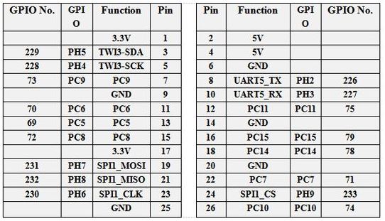
The SA818 transmit frequency is programmed via the UART5 serial port of the Orange Pi. It is not possible to change the frequency during the transmit phase.
Transmit command
The command to switch to transmission is not done by a simple change of state of an output of the GPIO of the Orange Pi for security reasons. In the event of a processor crash, the state of the output is not defined and the transmitter risks being blocked in transmission.
The web client sends an audio signal from the microphone sampled at 10 kHz and encoded in 2 bytes. These 2 * 10,000 samples, per second, are sent in packets of 512. This makes about 40 packets per second sent only in the transmission phase. Each time a package arrives, pin 26 changes state. This will generate a square signal, here in red, of 20Hz or a period of 50ms.

This square signal goes through a 4.7 μF capacitor and drives the base of a 2N2222 switching transistor and a 1n4148 diode. At each rising edge, the 2n2222 conducts and the collector voltage drops to around 0v. It is kept low, thanks to the 47 μF capacitor, after the falling edge which blocks the 2n2222. To the collector is connected a relay which switches the antenna signal to the SA818 in the presence of an input zero. This same signal via a diode 1n4148 is sent to pin 5 of the SA818 to make it go into transmission. A 10nF capacitor helps keep it low. This diode serves as protection so as not to exceed the 3v3 input. When transmission is stopped or in the event of a crash, the signal at output 26 of the GPIO remains blocked at 0 or 1. The signal on the collector will go back to 5v and the relay will switch to reception. The switching time is given by the 47 μF capacitor supplied by the 20 kΩ resistor and the control current of the relay. Depending on the relay used, it may be necessary to adjust the value of this resistor to maintain a 0 during the 50 ms and return to reception quickly when the square signal is stopped.
It is possible to replace this diagram by a monostable type CD4538 with a time constant of 100ms.

SA818 Pinout
Both models, VHF or UHF, have the same pinout.

Remote SDR application for SA818
The “Remote SDR” application processes various SDRs in transmission, such as HackRF or Adalm Pluto. In the case of the SA818, there are some specificities to adapt to its interfaces.
Programming transmission frequency
It is a serial link at 9600 baud, connected to the Uart5 port of the Orange Pi Zero 2. A python program receives the frequency order from the web client using websocket technology. This order is adapted to the format required for the SA818. The python application uses the pyserial-asyncio library installable by the commands:
apt install python3-pip
pip3 install pyserial-asyncio
The serial ports available on the card are given by:
dmesg | grep ttyfound in / dev / ttys5…
CTCSS code
The CTCSS code, useful for opening certain relays, is generated by the SA818 which receives, through the serial port, a channel number between 1 and 38 which corresponds to the frequency defined in the configuration table TX.js. This CTCSS code is not generated directly in the audio signal at the web client level as for other SDRs, because the SA818 cuts all signals below 300Hz.
Modulation by microphone audio signal
The microphone signal is digitized at the PC level by the web browser, then sent to the Orange Pi which outputs it in analog form on the 2 Line Out outputs. A python program built with the Gnu Radio Companion application performs the digital to analog conversion. The analog output level is set by the system audio mixer. Its level is defined each time the application is launched in the asound.state file in the PY folder. If you want to modify the modulation level, you must open the audio mixer in a terminal window with:
alsamixer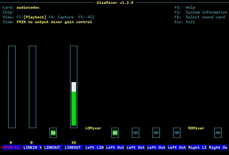
Use the arrows to adjust the ‘Line Out’ output level to adjust the modulation rate in NBFM. Once the correct setting has been found, saved it in the asound.state file with the command:
alsactl --file /var/www/html/PY/asound.state storeIf you want to test the audio output with a wav file:
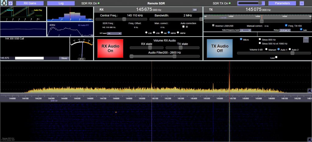
aplay -D hw:0,0 test.wavRemote SDR
Remote SDR, installs on the Orange Pi Zero 2. The application includes signal processing and the web server that provides the page to the web browser. The easiest installation is to download on Github, the Remote SDR image (at least version 3) for Orange Pi Zero 2 which includes the Armbian Bullseye OS and all the necessary libraries.
Please note that the ability to drive an SA818 is only available for Orange Pi Zero 2. Not to be confused with the Orange Pi Zero which is a 32-bit processor. Raspberry PI 4, used with other SDRs, which do not have an analog output directly, cannot interface with the SA818.
TX Amplifier
The output of the SA818 provides approximately 1W of signal. If you want more power, there are amplifiers on the market. Remember to add a band pass filtering to get rid of any parasitic signal that could be at the output of the SA818.
I tried to use this example with the Raspberry Pi 4 to switch the antenna relay. When I switched the TX on, the relay was switching very fast.
What can I do?
If you are using the system connected on pin 26, and your relay is switching rapidelly, increase the capacitor of 47uF on the collector of the transistor.
Regards, 73
I used a capacitor 330uF, then it works.
Thank you and 73
Gerhard, DK6RH
Perfect.
73
André
I have a Razpberry Pi4 4 model b-4gb and I can’t restore the SDR server program to it