Web based transceiver developped by F1ATB
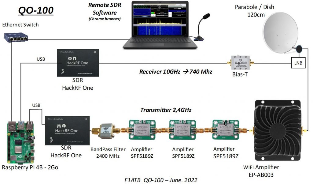
Below is the connection diagram of the various modules making up the transceiver allowing links to QO-100 with the “Remote SDR” application. I have been using this system since May 2020 with satisfaction. It has since been reproduced by many other Hams.
Reception chain
The antenna is a dish 1.20 m in diameter with an LNB head which translates signals from -9750 MHz in frequency. QO-100 signals received in the band 10,489,500 kHz – 10,490,000 kHz are reduced to the band 739,500 kHz – 740,000 kHz.
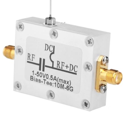
A “Bias-T” splitter sends the 12v power supply to the LNB and the HF signals to the receiving SDR (Hack-RF One).
The Hack-RF One is an SDR that covers a wide reception frequency range up to 6 GHz with 8-bit dynamic range, sufficient for traffic via QO-100 where the different signals are of a similar level. It is possible to replace the Hack-RF One with a classic SDR key which perfectly covers signals around 740 MHz, but does not allow you to listen to your own transmission around 2.4 GHz. The Hack-RF is connected to the Raspberry Pi-4B by USB which provides it with 5V power.
Transmission chain
The signal to be transmitted is generated by an SDR (Hack-RF One). It is mainly voice SSB for the QO-100 NB repeater. We can, with Remote SDR and other applications, generate other signals such as SSTV.
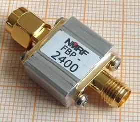
A band filter centered around 2.4GHz eliminates any out-of-band signals.
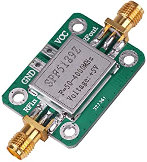
The generated signal being around the dBm, it is necessary to amplify with 3 amplifiers mounted in series (SPF5189Z), which are supplied with 5V. Each provides over 10dB of gain.
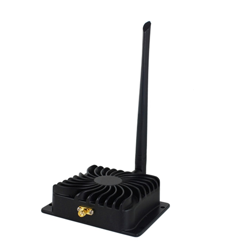
Finally, an amplifier (EP-AB003) from the WIFI field provides a few watts at 2.4 GHz. It is given for 8w but in practice, we must hope for about half.
The output signal is sent to a helix antenna in the center of the receiving dish.
Signal Processing
Signal processing in reception and transmission is provided by a Raspberry Pi 4B with 2 GB of memory. A downloadable image of the Raspberry OS operating system and Remote SDR fileset is available on Github. The Raspberry also serves as a web server to send Remote SDR pages to the web browser like Chrome or Edge.
Security Transmission
It is imperative to set up a device to avoid unwanted emissions in the event of a crash of the network, the Raspberry pi, etc., which would not allow orders to be placed.
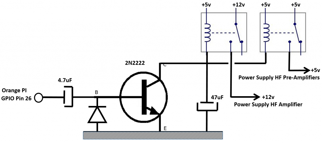
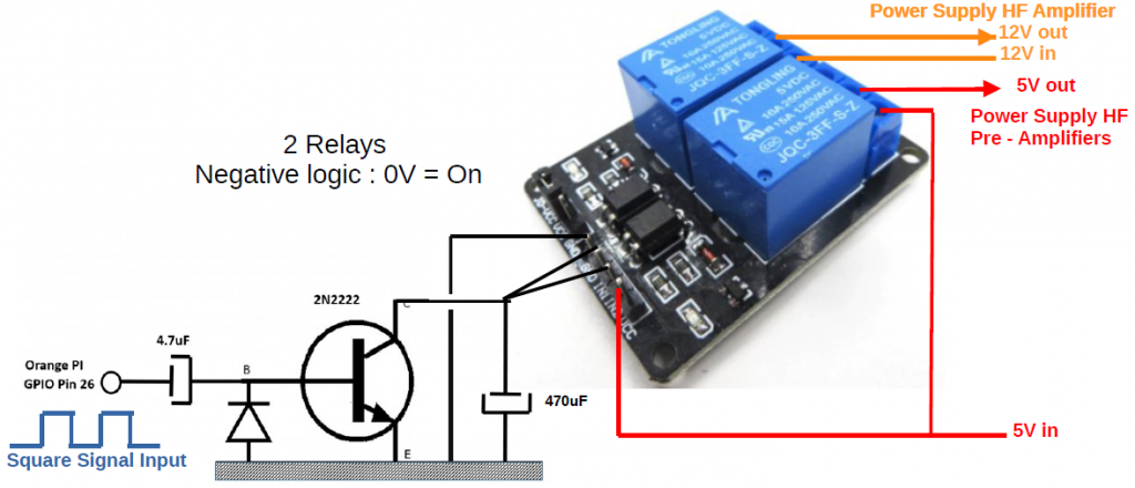
The Python3 module which receives the audio samples from the microphone in packets of 256 bytes causes pin 26 of the GPIO of the Raspberry Pi 4 to change state each time a frame is received. This creates a square wave AC signal (0v,3.3v) that is passed through a 4.7uF capacitor to a rectifier diode and switching transistor device such as a 2n2222. At each half cycle, the relays on the collector are operated and held by the 47uF to 470uF capacitor until the next half cycle. These relays switch the 12v power supply of the transmitter output WIFI amplifier and the 5v of the pre-amplifiers. Thus, if the audio frames are received, the power supply to the amplifiers is established. If the frames no longer arrive or the system crashes, pin 26 in the high or low position, the power supply is cut.
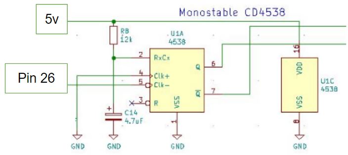
An alternative to the transistor circuit is to use a monostable like the 4538 which provides the Q and /Q outputs to drive any type of relay.
Assembly
All the subsets making up the transceiver are mounted in the case of an old PC. This allows for the necessary 12v and 5v power supplies.
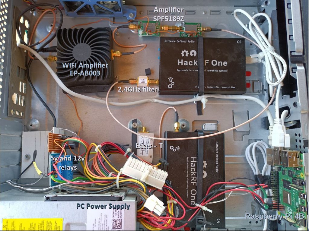
Realization in a PC box
Supply
The Raspberry Pi 4B with 2 GB of memory can be purchased from a local retailer. SDRs, amplifiers, 2.4 GHz filter and Bias-T can be found at Aliexpress China. Remember to also supply cables with SMA connectors to interconnect the modules.
This Post Has 18 Comments
Comments are closed.
What kind of software are you using to run the hack One in tx mode?
The TX software in Remote SDR is based on GNU Radio.
How much SPF5189Z modules should I use 2pcs or 3pcs?
During 1 year I used only 2. Since 6 months I used 3 and noticed a better HF level on QO-100.
I measured output of Hack RF @10dbm
One chinese amp ptoduces 100mW (20dbm)
The ones I bought limit at this level
73 Nick
I ws looking for your email to send you a photograph of my realisation of your QO100 Transceiver if you are interested?
73
Nick
LNB Offset
It was probably obvious to others but not yo me…
I could not get the upper and lower beacons in the right place.
Auto correct did not work so I manually adjusted the LNB offset from 9750000 to a value that set both beacons at the correct frequency.
I accidentally clicked auto correction and it moved miles away.
I then realised that in Andres settings the max and min error for QO100 are both negative.
I reset my LNB frequency to 9750000 and manually adjusted the offset to about +22kHz.
I then set the Min error at 0 and the max at +50000.
Now its perfect with my manual correction showing =22 713 Hz
A Eureka!!! moment for me.
Next trying to see how you adjust RX frequency on someone who responds to your CQ Call.
Loving the software
Tks for sharing Andre
Hi Nick,
After you changed the Min Max error settings, and manually adjusted the error to be close, is the Auto Correction now working for you now?
Yes it seemed to,
I use a standard Bullseye LNB.
I have tried turning everything off for a day and then powering u from cold.
It all came on frequency very quickly.
Leaving it monitoring GB2RS news on Sunday which os a long communication there is NO noticeable drift.
Very impressive.
73
Nick
Hi André,
i am just building a new setup QO-100 Web-TRX . I need a serious PTT signal to control an external PA. I would highly appreciate a signal from any GPIO of the RapsBärry that is precisely Hi or Lo during transmission.
Thank you for your nice software!
Regards
Herko, DK3HU
On the Settings page, you can define any GPIO which is free to switch to 1 or 0 when you transmit or receive.
Oh – that is a good solution.
Thanks for the information.
Regards and a merry christmas!
Herko
Hi Andre
There was a station working on QO100 tonight but working split frequenc.
Is it possible to do this with remote SDR?
ie. receiving on freq x but trabsmitting on freqx + say 15khz?
Thanks in advance
Nick
Yes you can do it. You use the manual correction of the transmitter to align the TX on the RX. When aligned, you add 15kHz to split the frequencies.
73
André
Hi André. We’ll build our own Transceiver, following the project of Yours. What kind of feeder are You using? Perhaps we’ll meet on the band. Vy 73 Jens
As the distance is short, I use an RG58 coaxial cable and the rest as described on the website.
73
André
using V5.0 and PlutoSDR for QO-100. RX is ok.
I have a difference of abt. 23 kHz in RX. How can I set man. correction and auto correction ?
I cannot select QO-100-up in TX window. It is always 432MHz.
Thanks
73 Uli, DF5SF in JN48mk
In the Setting page
Click on Modify button under Frequency Bands Error min Error max and set a frequency windows for the error.