The ESP32 is a very interesting microcontroller. It combines analog and digital inputs and outputs as well as WIFI and Bluetooth access. For its programming, there are different tools. Here, we will use the well-known tool dedicated to Arduino family microcontrollers which can be adapted to the ESP32.
IDE Arduino «Integrated Development Environment»
IDE Arduino
Go to the Arduino website https://www.arduino.cc/ and choose the ‘Software’ tab. Download and install the latest version of the development environment (IDE). Go to the “File” and “Preferences” menu and select your language.
The ESP32 is not part of the Arduino card family, it is necessary to add to the IDE a complementary library provided by the manufacturer “Espressif” which develops the ESP32. Go to File / Preferences and put the address: https://dl.espressif.com/dl/package_esp32_index.json

Choice of ESP32 board
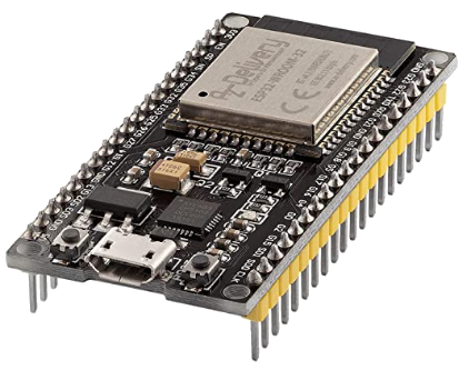
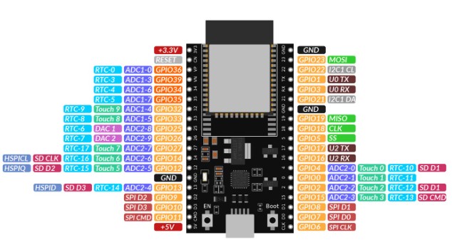
There are many boards on the market based on ESP32. It can sometimes be difficult to find the definition of the output pins (GPIO). Here we use a development board with an ESP32-Wroom and 2×19 pins. Purchase possible from Amazon, uPesy or from Aliexpress in China directly.
- ESP32 (3 choices)
- ESP32 38P (classic)
- ESP Wroom-32U with external WIFI antenna
- ESP32 Wroom DevKit v2 from uPesy in France
Loading a program and compiling
In the file menu you can:
- create a new program,
- use one of the many examples provided or,
- load a program that you have downloaded. For example the F1ATB photovoltaic router program
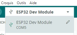
Connect the ESP32 card to your PC via the USB port. Select the ESP32 DEV Module board and the Windows serial (COM) port it connected to.

At the top, the first button only compiles the program to check that there are no errors. The arrow allows you to compile the source program, generate the binary and download it to the ESP32 card. It will be launched at the end of the download.
Complementary libraries
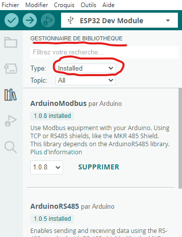
Many programs use program libraries that perform different functions. It is common during compilations to get an error message because a library is missing. We find the list of libraries included in your installation of the Arduino IDE on the left part of the screen.
If missing, do a search with the library manager and add the missing library.
Driver problem
It may happen that your ESP32 card is not recognized by Windows when connecting to USB.
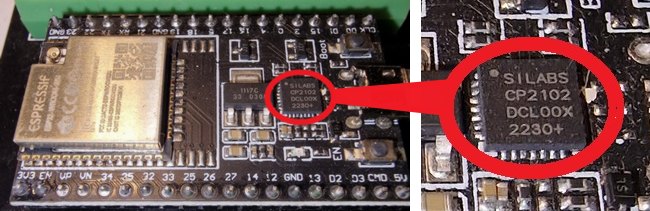
On the ESP32 card a component makes the serial/USB interface, the very common WCH340 or the CP2102 or CP2104. Look on the map. Windows does not know how to manage these drivers on its own.
It is perhaps the absence of a driver on the desktop PC which is responsible for the non-recognition
If it is a WCH340, the driver can be found here on its manufacturer’s website::
http://www.wch-ic.com/downloads/CH341SER_EXE.html 733
If it is a CP2102 or CP2104 ditto:
https://www.silabs.com/developers/usb-to-uart-bridge-vcp-drivers?tab=downloads
Choose the version corresponding to your OS; Windows…
Installation guide : https://techexplorations.com/guides/esp32/begin/cp21xxx/
Serial Monitor
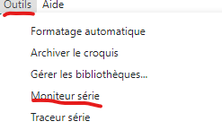
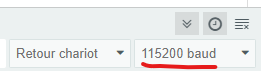
After a download operation, open the Arduino serial monitor by going to the Tools menu. Check to the right of the window that opened that you are at 115200 baud. The ESP32 will provide you with a lot of information such as the IP address assigned to it, etc.
Loading a program via OTA
Generally, you install a program on an Arduino or an ESP32 via the USB serial port. As the ESP32 has WiFi, we can integrate an “OTA” (On The Air) or Radio software module into the application code. This allows you to download and update a program via WIFI and not the USB cable.
The photovoltaic router (F1ATB) integrates this functionality in order to make updates remotely.
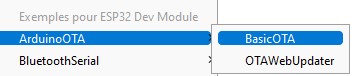
If you want to try out an OTA example, there are many available in the Arduino IDE. In the examples, select the “Basic OTA” program.
Modify the program slightly by specifying the IP address for your ESP, the SSID (WiFi name)…
#include <WiFi.h>
#include <ESPmDNS.h>
#include <WiFiUdp.h>
#include <ArduinoOTA.h>

const char* ssid = "YOUR SSID";
const char* password = "THE PASSWORD";

// Set your Static IP address
IPAddress local_IP(192, 168, 0, 208); //HERE DEFINE YOUR IP ADRESS
// Set your Gateway IP address
IPAddress gateway(192, 168, 0, 254);  //DEFINE THE GATEWAY

IPAddress subnet(255, 255, 255, 0);
IPAddress primaryDNS(8, 8, 8, 8);   //optional
IPAddress secondaryDNS(8, 8, 4, 4); //optional
Download the code the first time via serial link. Pressing the RST button allows you to thoroughly test everything. At this point, you will be able to update the programming via the web by no longer choosing the serial port in the Arduino IDE, but the network port, in our case 192.168.0.208. In your code, you will need to integrate the ArduinoOTA part in order to maintain this possibility. When loading, the IDE will ask you for a password. Reply any letter.
Remote “Debug”
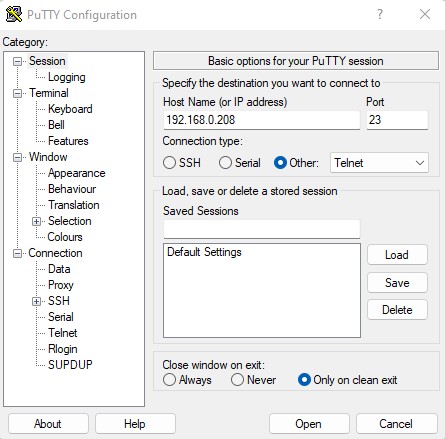
By using WiFi you will lose the possibility of debugging via the serial port. The “RemoteDebug” library will allow you to find this possibility following 2 possibilities:
- Telnet listening on port 23.
- using the RemoteDebugApp application, download here:https://github.com/JoaoLopesF/RemoteDebugApp
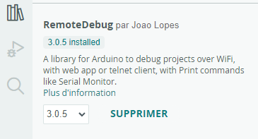
To use this debug functionality, you must first install the RemoteDebug library by Joao Lopes in the Arduino IDE, which will also install usage examples.
OTA and Remote Debug are 2 features implemented in the F1ATB Photovoltaic router software. There is nothing to do except install the RemoteDebug library in the IDE.