Remote Keys
Remote SDR, application for controlling a transceiver from a web browser, can now (version> = 4.1) connect via USB to:
- a frequency controller by rotary button
- a Morse code manipulator interface
- a push button to switch to transmission
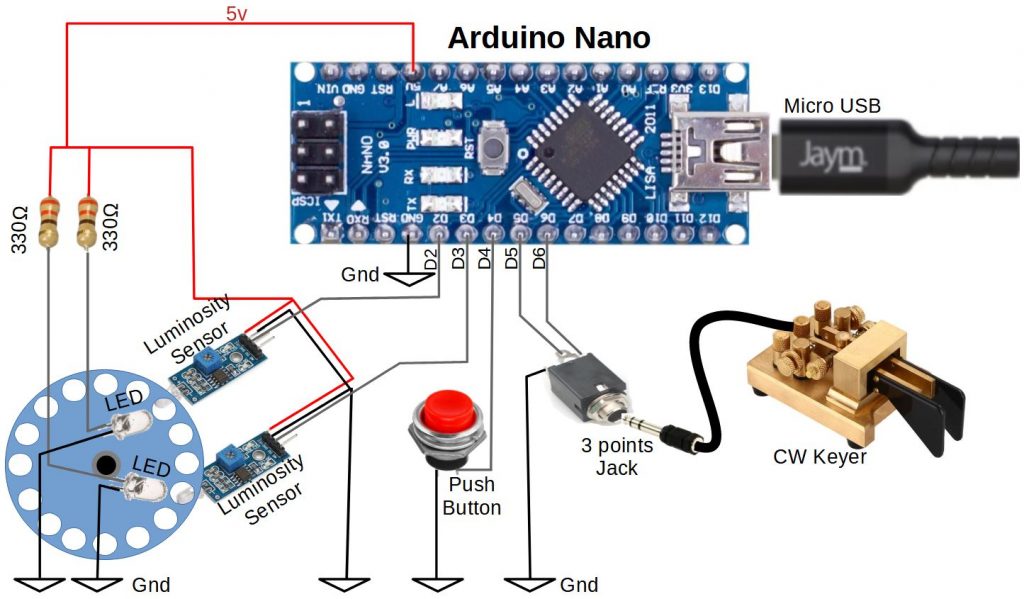
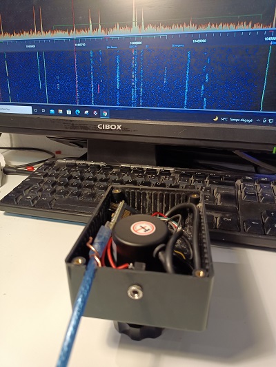
This system, “Remote Keys”, is built around an Arduino Nano microcontroller which collects datas and transmit them via USB to Remote SDR, which uses the “Web Api” interface as described here.
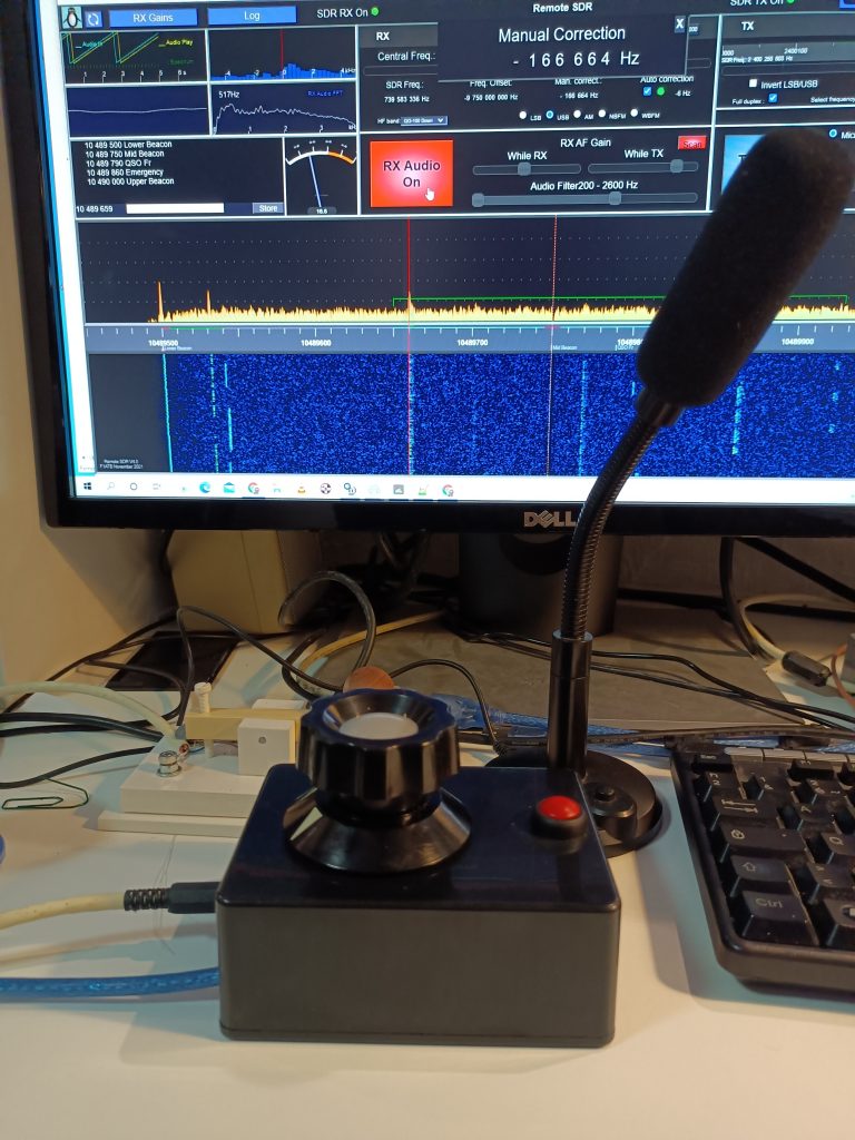
The set is mounted in a box with a large frequency control button on top and a push button to transmit. On the side, a jack socket allows a telegraphy manipulator to be connected to one or two paddles.
Hardware
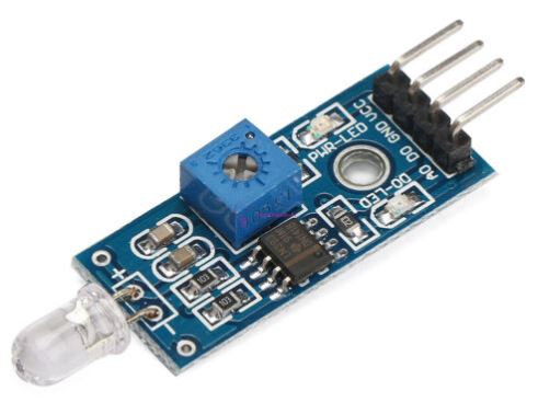
The frequency control button alternately lights up when turning, 2 brightness sensors which provide 2 digital signals on the D2 and D3 inputs of the Arduino Nano. A push button between ground and D4 allows to change state between transmission and reception, at each press. Inputs D5 and D6 receive digital signals from the Morse manipulator paddles.
The arduino Nano is connected to the PC running Remote SDR in a recent browser like Chrome or Edge capable of processing the Web Serial API.
Power for the assembly is supplied by USB.
Rotary Knob (DIY Version)
There are rotary knobs on the market that provide 2 compatible digital signals from an Arduino. Unfortunately, they typically only provide about 20 states per 360 ° turn. For ease of use, you need many states per revolution to quickly scan a band. Likewise, a heavy button, with a certain inertia, enables rapid sweeping by rotating it.
For this project, I built a 7cm diameter epoxy wheel drilled with 16 6mm holes on the periphery and a 6mm central hole to pass a rotation axis. Two LEDs, above two light sensors, lit or not depending on the position of the wheel, provide an output at 0 or 1. They must be placed judiciously to have a change of state on each sensor alternately in a sequence:
00, 01, 11, 10, 00,… ou 00, 10, 11, 01 , 00… according to the direction of rotation.
An adjustment by potentiometer, makes it possible to adjust the luminosity threshold for switching. 0, 1. The 16 holes allow 64 state changes per 360 ° turn.
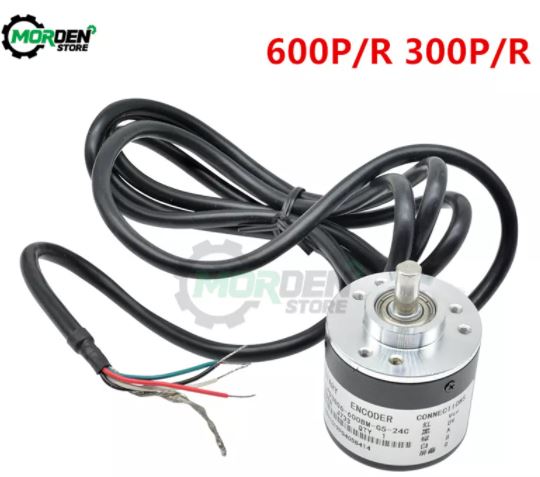
Rotary Knob (Chinese version)
By looking a little we find optro coders on the Chinese market (Aliexpress) at a very good price (10 €). Take the model at 300 or 600 pulses per revolution. The output signals (in open collector) are identical to those of the personal model, namely 2 phase-shifted oscillations which directly attack inputs D2 and D3. The button is supplied between + 5V and ground.
Push Button
A simple push button allows the passage in transmission like the TX Audio On / Off button of Remote SDR.
Morse Manipulator Input
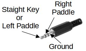
Two digital inputs (grounded or not) allow the connection of a manipulator with one or 2 paddles. A 3.5mm 3-point jack plug is used.
Software
The software installed in the Arduino is very simple. It only transmits state changes. No command is received from Remote SDR. If you do not want the 3 functions: the knob, the push-button and the Morse manipulator, all you have to do is set to 0 the corresponding inputs or simplify the code. I will not detail here, how to develop code for Arduino, there are hundreds of tutorials on the subject. I just provide the source below:
/*
  Remote SDR
  Interface Serial-USB
  - Frequency Tuning
  - TX/RX state change
  - CW Key
  F1ATB 26 December 2021
*/

// digital pin 2 and 3  has a luminosity sensor attached to them.
int Led_A = 2;
int Led_B = 3;
// digital pin 4 has a pusbutton attached to it
int pushButton = 4;
int OldButton = 1;

//CW Key
int LeftKey = 5;
int RightKey = 6;
int OldLeft = 1;
int OldRight = 1;

int Delay = 1;

int total=0;
// the setup routine runs at start up
void setup() {
  // initialize serial communication at 115200 bits per second:
  Serial.begin(115200);
  // make the pushbutton's pin an input:
  pinMode(Led_A, INPUT_PULLUP);
  pinMode(Led_B, INPUT_PULLUP);
  pinMode(pushButton, INPUT_PULLUP);
  pinMode(LeftKey, INPUT_PULLUP);
  pinMode(RightKey, INPUT_PULLUP);
  attachInterrupt(digitalPinToInterrupt(Led_A), A_Rising, RISING) ;

}

// the loop routine runs over and over again forever to read the button and the morse key:
void loop() {
    Delay = 1;

    // Read PushButton
    int Button = digitalRead(pushButton);
    if (OldButton != Button) {
        Serial.println("B"+String(Button));
        OldButton = Button;
        Delay = 10;
    }

    // Read LeftKey
    int kLeft = digitalRead(LeftKey);
    if (OldLeft != kLeft) {
        Serial.println("L"+String(kLeft));
        OldLeft = kLeft;
        Delay = 2;
    }
    // Read RighttKey
    int kRight = digitalRead(RightKey);
    if (OldRight != kRight) {
        Serial.println("R"+String(kRight));
        OldRight = kRight;
        Delay = 2;
    }
    // Total is the sum of impulsions received from the rotating knob
    if (total<0){
       Serial.println("D"+String(total));
       total =0;
       Delay = 10;
    }
    if (total>0){
       Serial.println("U"+String(total));
       total =0;
       Delay = 10;
    }
    delay(Delay);        // delay in between reads for stability
}
void A_Rising() { // Rotating Knob interruption
    int LedStateB = digitalRead(Led_B);
    if (LedStateB ==0){
      total--;
    } else {
      total++;
    }
}
In this new software version, the button triggers an interrupt on a rising edge of pin D2. The Arduino counts up or counts down the edges depending on the state of pin D3. The total is sent for processing via the serial link. The use of interrupts helps to properly count the pulses when throwing the knob in rapid rotation.
When the push button is pressed, the Arduino sends “B0”. When released, “B1”.
A press on the left pallet or the simple manipulator, an L0 is sent. On release L1. For the right palette, it is R0 and R1.
The serial link is at 115200 bits / second so as not to take too much transmission delay.
Construction
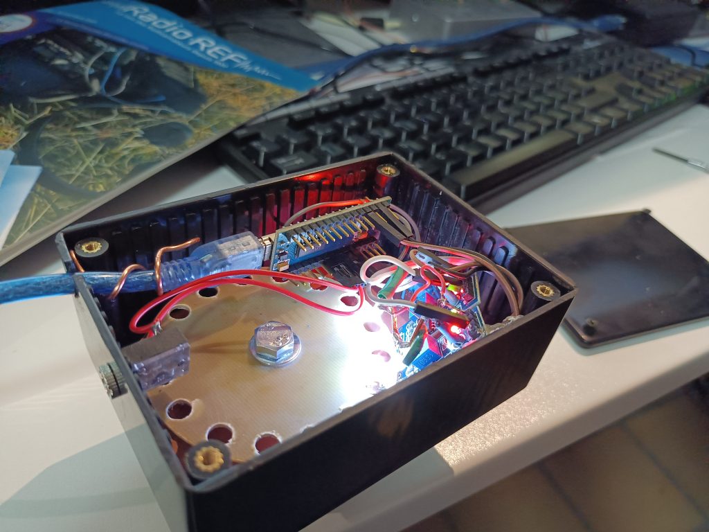
The assembly is mounted in a light-tight box so as not to disturb the operation of the light sensors.
The components (Arduino, Brightness sensors) can be found on Ebay or Aliexpress.
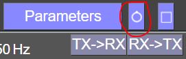
To define the USB port to connect to, click on the button at the top right.
Hello Andre
great project ! this tunning knob
but why no use some optical encoder such as https://www.aliexpress.com/item/32961497880.html?spm=a2g0o.productlist.0.0.5b8930daCUXVVG&algo_pvid=2b2b90a9-8cdc-42d5-8236-f6932b3d4cd2&algo_exp_id=2b2b90a9-8cdc-42d5-8236-f6932b3d4cd2-11&pdp_ext_f=%7B%22sku_id%22%3A%2266512166308%22%7D
73 Frans PE0F
https://www.aliexpress.com/item/4001127790592.html?spm=a2g0o.productlist.0.0.5b8930daCUXVVG&algo_pvid=2b2b90a9-8cdc-42d5-8236-f6932b3d4cd2&algo_exp_id=2b2b90a9-8cdc-42d5-8236-f6932b3d4cd2-33&pdp_ext_f=%7B%22sku_id%22%3A%2212000016592518955%22%7D
or this one ?
Interesting alternative solution. I did one myself, as I had all the components.
The software, I propose for the Arduino is very simple and can be adapted to different encoder.
I will look if i can make it work 😉
Can you please adapat the code to a 600p/r ? I myself I am not a programer
The last version online works with a 600p/r.
If it’s too sensitive, tell me, I will reduce by 2 or 4 the number of pulses per tour.
73
André
lets go for 10 since your sensor setup was 60p/r ? we should as get close to your great selfmade rotory
If possible make it some parameter, but this could be on the wishlist
And a very Merry Happy Christmas!
73 Frans
In the version 4.2 to be released within 1 week, I will put in the configurationRX.js file a velocity factor to adapt, with only one coefficient, the speed of the rotating knob.
73
André
Marvelous !
On 26 december, I have updated the software. Now, it used the interruptions to perfectly counts the pulses when you throw the knob in rapid rotation. With the 600 pulses per revolution knob, it works fine.
Great many Thanks and Happy New Year for you and your family I wil wait for the final release of 4.2
73 Frans
I have built the controller, and used the program as listed on the page. There are sme starnge things happening when usint the unit. Sometimes the cselected frequency “spins off” to an unknown value. The cuse of this is the deklaration of the variable “total”. When interrupt routines changes a variable, the varialble must be decalred like this:
volatile int total=0; or volatile static int total= 0;
Then the program on the arduino will change the frequency “like a dream”….
Karl
I have noticed your remark about this bug. I will fix it.
73
Hi!
I have rewritten the handling of the rotary encoder, now it workes flawlessly! I have used a library called Rotary Encoder. Please have a look here: https://www.mathertel.de/Arduino/RotaryEncoderLibrary.aspx. The library is installed via the library manager. Look for “Rotary Encoder – Matthias Hertel”. 73s de Karl
New code:
/*
Remote SDR
Interface Serial-USB
– Frequency Tuning
– TX/RX state change
– CW Key
F1ATB 26 December 2021
20. feb. 2024
Handling the rotary encoder totally rewritten
LA3FY
*/
#include
#include
#define PIN_IN1 2
#define PIN_IN2 3
// digital pin 4 has a pusbutton attached to it
int pushButton = 4;
int OldButton = 1;
//CW Key
int LeftKey = 5;
int RightKey = 6;
int OldLeft = 1;
int OldRight = 1;
int Delay = 1;
// A pointer to the dynamic created rotary encoder instance.
// This will be done in setup()
RotaryEncoder *encoder = nullptr;
void checkPosition()
{
encoder->tick(); // just call tick() to check the state.
}
void setup()
{
Serial.begin(115200);
// make the pushbutton’s pin an input:
pinMode(pushButton, INPUT_PULLUP);
pinMode(LeftKey, INPUT_PULLUP);
pinMode(RightKey, INPUT_PULLUP);
// setup the rotary encoder functionality
// use FOUR3 mode when PIN_IN1, PIN_IN2 signals are always HIGH in latch position.
// encoder = new RotaryEncoder(PIN_IN1, PIN_IN2, RotaryEncoder::LatchMode::FOUR3);
// use FOUR0 mode when PIN_IN1, PIN_IN2 signals are always LOW in latch position.
encoder = new RotaryEncoder(PIN_IN1, PIN_IN2, RotaryEncoder::LatchMode::FOUR0);
// use TWO03 mode when PIN_IN1, PIN_IN2 signals are both LOW or HIGH in latch position.
//encoder = new RotaryEncoder(PIN_IN1, PIN_IN2, RotaryEncoder::LatchMode::TWO03);
// register interrupt routine
attachInterrupt(digitalPinToInterrupt(PIN_IN1), checkPosition, CHANGE);
attachInterrupt(digitalPinToInterrupt(PIN_IN2), checkPosition, CHANGE);
} // setup()
void loop()
{
static int pos = 0;
static char direction=’U’;
Delay = 1;
// Read PushButton
int Button = digitalRead(pushButton);
if (OldButton != Button) {
Serial.println(“B”+String(Button));
OldButton = Button;
Delay = 10;
}
// Read LeftKey
int kLeft = digitalRead(LeftKey);
if (OldLeft != kLeft) {
Serial.println(“L”+String(kLeft));
OldLeft = kLeft;
Delay = 2;
}
// Read RighttKey
int kRight = digitalRead(RightKey);
if (OldRight != kRight) {
Serial.println(“R”+String(kRight));
OldRight = kRight;
Delay = 2;
}
encoder->tick(); // just call tick() to check the state.
int newPos = encoder->getPosition();
if (pos != newPos) {
if (((int)(encoder->getDirection()))<0) {direction='D';}
else
{direction='U';}
Serial.print(direction);
Serial.println(newPos-pos);
pos = newPos;
} // if
delay(Delay); // delay in between reads for stability
} // loop ()
Thank you
….ooops, I forgot to comment an impartant line:
void loop()
{
static int pos = 0;
static char direction=’U’;
Delay = 1;
// Read PushButton
The “Delay = 1; line in the beginning of the loop. Here you can adjust the “sensivity”. With the value = 1, it’s very hard to more than 20-30Hz change in frequency. Increasing the value will result in bigger frequency syeps when turning the encoder fast. I have not tried a 600 pulses/rev encoder. The one I’m using gives 100 pulses/rev and workes fine.
https://www.aliexpress.com/item/32754734330.html?spm=a2g0o.order_list.order_list_main.20.39da1802SIXh6l
73s de Karl LA3FY
Hi Karl! Tried to compile but cimpillation error with :
*/
#include
#include
Filename ?
Sergey
R5AU
oh…! I see that the name of the include files are missing.
#include
#include
I think adding these lines helps! Install the library mentioned in previous posting. Use the library manager in Arduino IDE and search for “Rotary Encoder” by Matias Hertel.
Good luck!
Karl
The names of the headers are removed when posting…
#include Arduino.h
#include RotaryEncoder.h
The headers should be inclosed in a “lesser than” sign and a “bigger than” sign. These two letters will not show up. I suppose this has to do with html.
I hope you get it working Sergey! If not, please tell me, and I will provide a link where the file can be downloaded!
Karl
Hi Karl !
Sorry for delay, i am not programmer but to many syntaxis error while compilation.
argue of #include should be in double brackets. I put sketch and compilation output are here:
https://cloud.mail.ru/public/mEUZ/ZKiZmiMUe and will be grateful in case you will look into.
In case feed back to can mail to me on r5au@outlook.com
Thank you !
The sketch in a previous post does not work. A lot of letters are inserted when just copying to this blog. I have zipped the sketch and the file can be downloaded here:
https://kj.skontorp.net/RemoteSDR/
Letters in the URL are case sensitive.
73s de Karl