Remote SDR V1 – Signal Processing
“Remote SDR” which allows remote control of an ham radio receiver and transmitter runs on a web browser such as Chrome or Edge (2020 versions). It is written in HTML and Javascript. The latter allows powerful processing such as Audio filtering or Fourier Transforms to perform spectral analysis in real time. HTML and associated style sheets make it easy to adapt the interface to user needs.
Remote SDR remotely manages a receiver and a transmitter simultaneously via 2 processors from the Orange PI family (Chinese nano processor similar to the Raspberry Pi). The connection is made via the local area network LAN. I prefer the wired network to WIFI subject to cuts.
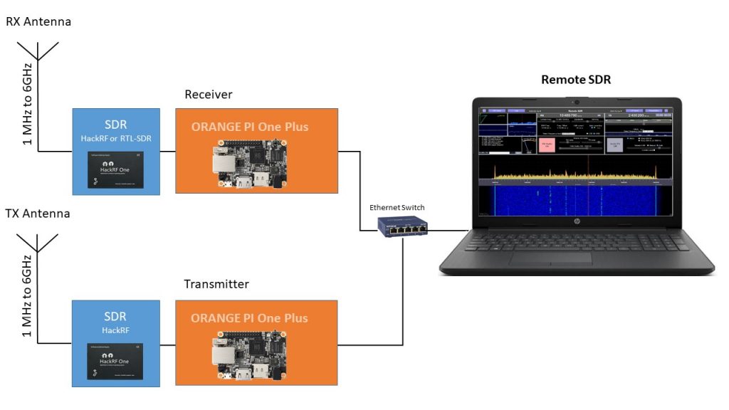
Receiver process
The start of the receiver processing is performed in the Orange Pi and is described in the article Remote SSB receiver. 2 data streams come out:
- an audio stream: a channel sampled at 10 kHz
- a spectral analysis stream:2048 points covering the processed band of the receiver, 5 times per second.
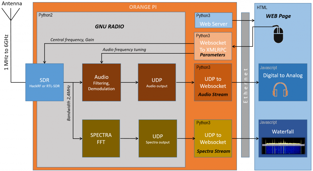
Receiver Audio channel

The audio signal coming from the Orange PI enters the processing by the network according to the websocket protocol. The input stream is composed of packets of 1024 bytes, or 512 audio samples encoded on 16 bits and sampled at 10kHz. The processing that follows is synchronous with the audio card of the PC or the display tablet which samples the signals at typically 44.1 or 48kHz. The first stage of the processing is an interpolation to go from 10 kHz to 44.1 or 48kHz. In the mean time, whole 16-bit samples are converted to floating point numbers and multiplied by the desired volume control. Since samples come in asynchronously in packets of 512, a buffer stores them for a few ms, before the Web Audio API plays them synchronously with the sound card. A high pass filter followed by a low pass filter redefines the listening band between 100Hz and 4000Hz. The original signal output from the Orange Pi is between 200 and 3900 Hz.
The audio signal sent to the loudspeaker or the headphones is represented in temporal form by a small oscilloscope and a Fast Fourier Transform (FFT) allows to have a spectral view. This will be useful to subsequently set the transceiver’s transmit frequency to the receive frequency.
Reception band spectrum
The second stream at the output of the orange PI consists of a spectral analysis on 1024 points covering the received band of 150, 300, 600, 1200 or 2400kHz. This practically gives a useful band taking into account the filtering on the edges of 125, 250, 500, 1000 or 2000kHz. The data received are directly logarithms of amplitudes. 10dB corresponds to a difference of 100 in amplitude.

At each arrival of a frame of 2048 amplitudes of the spectrum, they are immediately converted into luminosity levels to draw a line of pixels on the waterfall canvas. Each of the amplitudes is averaged by a first order RC filter:
Yn = a * Xn + (1-a) * Yn-1 avec a=0.1
The plot of the instantaneous spectrum of the 1024 amplitudes covering the received frequency band is made from the direct values or those averaged. I prefer averages that smooth out noise.
These averaged channel values make it possible to estimate the signal level above the noise on the audio channel axis to give a reception ratio.
AUTOMATIC FREQUENCY DRIFT COMPENSATION
These averaged channels also make it possible to estimate the fine frequency of a beacon to automatically correct the frequency error of the reception chain. This finds an interesting application in the case of reception from the QO-100 satellite. It makes it possible to compensate for the error introduced by the frequency drift of the PLL of the reception head. The estimate is recalculated every second and sent to the SDR to compensate for the drift. If a beacon is in the center of the spectrum, it is not taken into account because the central channel of the SDR is subject to level errors due to the disparities between the I and Q chains.
Parameters to receiving SDR
It is necessary to send periodically or at each change of parameters to the receiving SDR and the processing in the Orange PI. They are 7 in number:
- the central frequency of the SDR between 1 MHz and 6 GHZ for a Hack RF One.
- the bandwidth to be processed between 150 and 2400kHz
- the fine frequency of the audio channel
- BLI or BLS mode (Lower or Upper sideband)
- 3 gains for the SDR (not all are necessary depending on the chosen SDR).
Transmitter process
The transmission processing chain is mainly processed in the Orange Pi connected to the transmission SDR. Its description is given in the article Remote SSB transmitter.
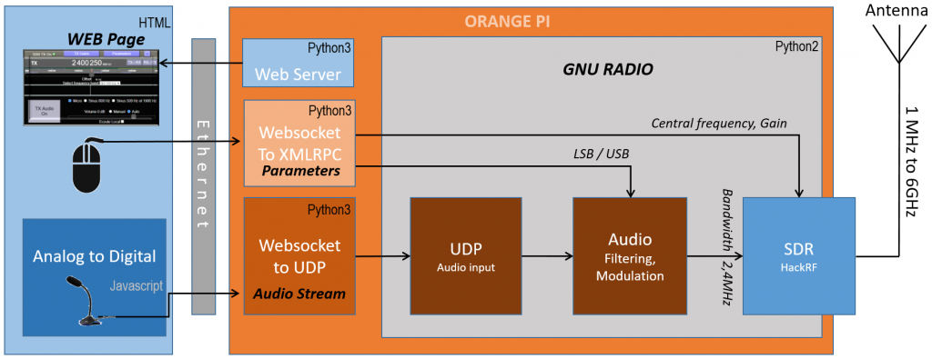
The Orange PI must be supplied with an audio stream from the microphone sampled at 10kHz on 16 bits.
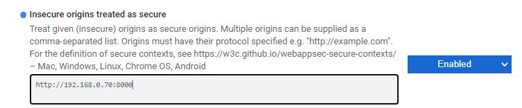
The Web Audio API provides us with all the functions in Javascript to retrieve the audio from the microphone connected to the PC. Unfortunately, security rules at the level of web browsers do not allow the microphone signal to be recovered if the web server which provides the page does not have secure access in https. On your local network at home, you generally work in http simply. To get around this difficulty, the solution is to set up a derogation at the web browser level by accessing the “flags” parameters. If the server which provides the remote_sdr.html page is for example at the IP address 192.168.0.70:8000, you must type in the address bar:
with Chrome: chrome://flags
with Edge(2020): edge://flags
Look for:
Insecure origins treated as secure
Fill in the field as below:
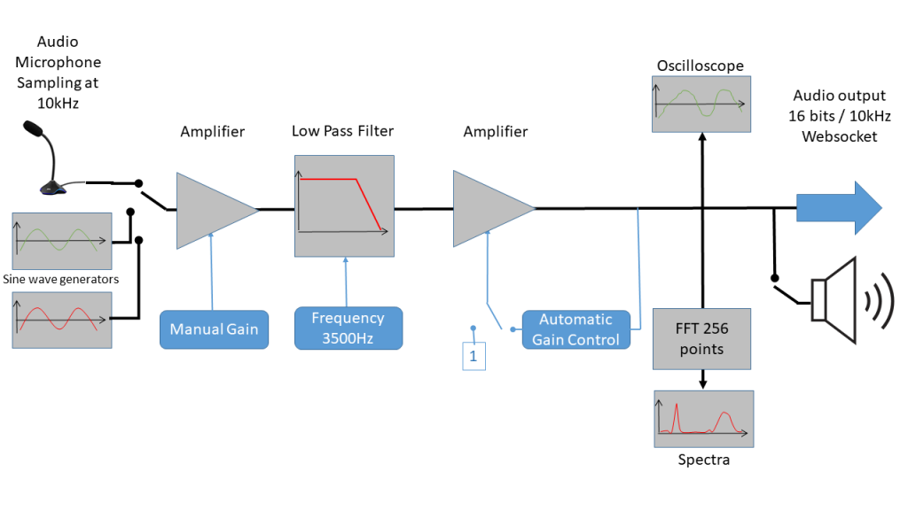
For the transmitter, there are 3 audio sources:
- a microphone input from the PC or tablet
- a sinusoidal source at 800Hz
- two sinusoidal sources at 500 Hz and 1900 Hz
The 800Hz source is used to test the level of the power chain and to adjust the transmission frequency to the reception frequency by checking that on the received spectrum there is a line around 800Hz.
The dual source at 500 and 1900Hz makes it possible to verify the correct linearity of the transmitter with the test called “2 tones test”. If the spectral analysis gives intermodulation lines at 1900-500Hz or 1900 + 500Hz etc, this reflects a non-linearity.
Behind an amplification whose gain can be adjusted is a low-pass filter to limit the audio frequencies to 3500Hz. Subsequently it will be filtered again in a 200Hz – 2800 Hz band suitable for SSB.
Finally, another amplification stage makes it possible to adjust the levels in order to be perfectly framed on the 16 bits of each sample sent to the Orange PI and to the SDR. It is best to stay in automatic gain mode so as not to have over modulation which results in a sprawling HF spectrum.
To monitor its audio signal, there is a temporal and spectral view of the signal as well as the possibility of listening locally.
Following the websocket protocol, the audio data is sent to the Orange PI. As a reminder, the arrival of the audio stream enables the HF amplifiers to be switched on as part of the construction for the QO-100 / ES Hail2 satellite.
Parameters to transmitting SDR
There are five configuration parameters sent to the Orange Pi and the SDR:
- the transmission frequency between 1MHz and 6GHz
- LSB or USB mode
- 3 HF gains for the different stages of SDR Hack RF One.
RX and TX configuration
The parameters for configuring the receiver and the transmitter are saved as:
- permanent settings
- modifiable settings
The permanents are saved in 2 javascript files:
– configurationRX.js
– configurationTX.js
There are the working frequency bands, for example 7 to 7.2MHz or 144 to 146 MHz or 10.4895 to 10.490 GHz. Frequency offsets if, for example, an LNB head is used. The labels to put under certain frequencies as beacons etc.
Modifiable settings such as BLI or BLS mode, the last frequency listened are stored at browser level in the “Local Storage”.
Posts on Remote-SDR
- Remote SDR V5 -Raspberry 4B or Orange Pi Image Installation
- Remote SDR v5 – Manual Installation
- Remote SDR v5
- QO-100 Satellite Live
- RTTY
- Troubleshooting
- QO-100 Transceiver
- SSTV
- WSJT-X – FT8
- Omnirig – Remote SDR
- Communication Ports
- Tone generators
- Setting of GPIO outputs
- Band Scanning
- Gains and Dynamics
- Frequencies Management
- Launch of Remote SDR
- CPU Cooling
- Web GUI
- Microphone and signal processing authorization
- Configurations
- Characteristics
- Introduction to Remote SDR
- Remote SDR – Audio Channels
- CW with Remote SDR
- Rotary Knob and Morse Manipulator for Remote SDR
- VHF and UHF NBFM Transceiver
- Remote SDR v4
- Gpredict — Remote SDR
- Remote SDR V4 – Raspberry Pi 4B or Orange Pi Zero 2 image installation
- Remote SDR v4 – Manual Installation
- SA818 – RTL-SDR
- Remote SDR – Examples of realization
- Transmit over QO-100 satellite with a Smartphone
- Remote SDR V2 – Software Architecture
- Remote SDR V1- Purchase
- Remote SDR V1 – Man Machine Interface
- Remote SDR V1 – Signal Processing
- Web Client to GNU Radio
- GNU Radio to Web client
- Remote SSB Transmitter
- Remote SSB Receiver
- GPIO on Orange PI One Plus H6
- TCXO installation on HackRF
- Q0-100 Transceiver with 2 SDR – Remote SDR V1


Recent Comments