Version V2
With solar panels, in a self-consumption installation, it is common to have overproduction of energy which we do not know what to do with and which is sent to the grid. A solution to store this excess is to send it to the electric water heater.
A quick calculation, for a 200l water heater, equipped with a 2400W heating resistor, shows that it takes nearly an hour of heating, or 2.3 kWh to raise the water by only 10°.
200l*1000gr*4.18Joule*10°/3600s=2322 Wh = 2.3kWh
Every day, several kWh must be supplied to the water heater. For a conventional system, this is done at night at a reduced rate. In the event of overproduction during the day of the photovoltaic panels, this energy must be sent to the water heater. It is a superb energy storage battery. But it is common to have only a few hundred watts available and not the power of 2400 w required by the resistance of the water heater in conventional connection.
Here, we are going to make a system that sends only excess power to the water heater by monitoring the power that enters or leaves the house so that it is zero using a current sensor connected behind the meter. This system only works for classic electric water heaters in which there is an electrical resistance and an electro-mechanical thermostat to control the temperature.
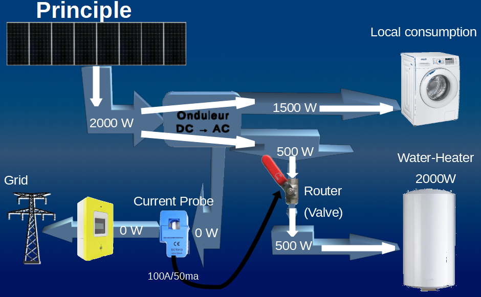
The solar router acts as a valve that opens to let the overproduction pass by monitoring the current entering the house so that it is zero.
Hardware
To complete the set, you will need the following hardware :
Current Sensor
To measure the current entering the house, a current sensor is used through which the mains phase wire is passed. At the output, acting like a transformer, it provides an identical current, but 2000 times lower. This current is sent across a resistor and we will measure the voltage generated.
There are different models depending on the Max current that you want to measure. The 100A version is suitable for a home with a maximum power delivered of 12kVA. It is found in China at Aliexpress.
Voltage sensor
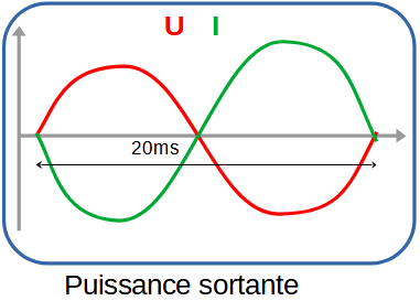
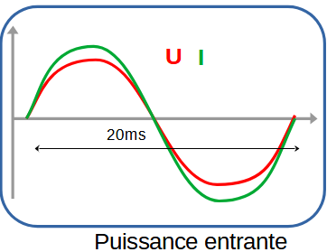
To know if energy is entering or leaving the house, the electrical voltage must also be measured. It is by comparing the phase of the current I and the voltage U that we will know the direction of the energy transfer.
To measure the voltage, we use a classic wire-wound step-down transformer that isolates us from the mains. For example a 230v/6v. We need a model as small as possible, we do not take any power. It’s not very easy to find anymore. A transformer, called bell, can do the trick.
Microcontroler
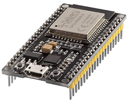
To perform voltage measurements and calculations, the ESP32 is a microcontroller adapted to our needs. It contains :
- analog inputs for measuring voltages,
- digital inputs/outputs to activate a relay or a triac if necessary,
- good calculation skills
- a WIFI connection for remote reporting on a web page or a home automation system.
Dimmer – Triac
To adjust the current to be injected into the water heater, a dimmer from RobotDyn is used, consisting of a Triac and a voltage zero crossing detection system. It exists in 16A or 24A and is available from Aliexpress.
Be careful, the original Triac heat sink is undersized knowing that it will have to operate for several hours. Add aluminum elements or replace it with a larger one.
In addition to a dimmer, you can optionally add 1 or 2 solid relays to activate other devices if necessary.
Current and Voltage Measurement
The measurement of the 2 voltages representing the current and the mains voltage is done by the analog inputs of the ESP32. These inputs accept a positive voltage between 0 and 3.3V and digitize the value on 12 bits, values between 0 and 4095. To adapt to the input dynamics, a voltage reference is created in the middle of the range at 1.65V =3.3V/2 to which the output voltage of the transformer and the current probe will be added.
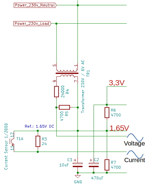
We take the 3.3V from the ESP32 which, passing through a bridge of 2 resistors (R6 and R7) of 4700 ohm connected to ground, provides us with a reference of 1.65V in the middle. To avoid measurement noise, a 470uF capacitor (C2) filters the 3.3V and another 10uF (C1) filters the midpoint at 1.65V.
In order not to exceed 3.3V peak to peak of the signals to be measured, or 1.65V peak, we set a limit of +-1V maximum effective.
For the current probe with 80A and a 24 ohm resistor, we arrive at approximately 1V peak to peak.
24*80A/2000=0.96V rms or 1.36V peak to peak.
Thus the voltage to be measured will be in the range 1.65V +/- 1.36V.
At home, with a 12KVA subscription, I should not exceed 60A.
Pour la mesure de tension, il faut mettre un pont de résistances (R4 et R5) pour abaisser le 6V autour de 1V efficace et avoir ainsi un signal à mesurer entre 1.65V +/- 1.41V.
Wiring to ESP32
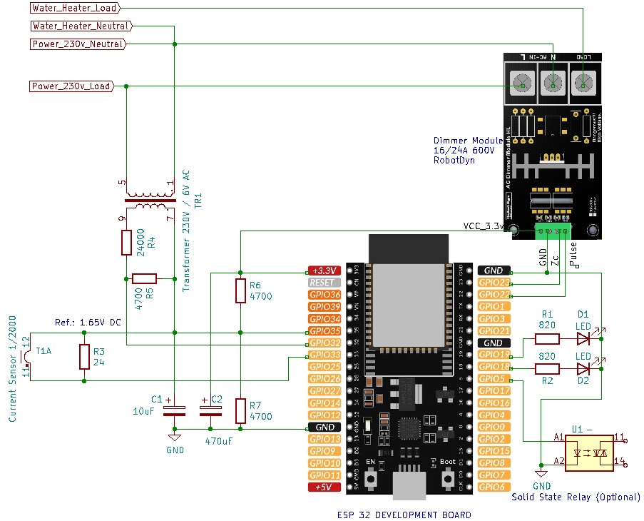
The treasure hunt with these cards that integrate an ESP32, is to find the GPIOs available and not used for Flash programming etc.
In our case, we measure the following voltages:
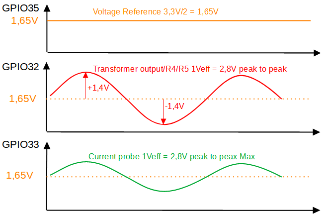
- GPIO 35: the reference voltage at 1.65V in theory.
- GPIO 32: the output voltage of the transformer reduced by the bridge of resistors R4 and R5
- GPIO 33: the voltage representing the current to be measured
2 LEDs on GPIOs 18 and 19 flash every 2s. The yellow if we consume current, the green if we supply current, because we are in overproduction.
The control of the dimmer is done via the GPIO22 and the reading of the zero crossing pulse “Zero Crossing” of the mains voltage on the GPIO23. This pulse is essential to synchronize with the mains.
As an option, you can for example connect a solid controllable 3.3V relay to the GPIO5.
Timing
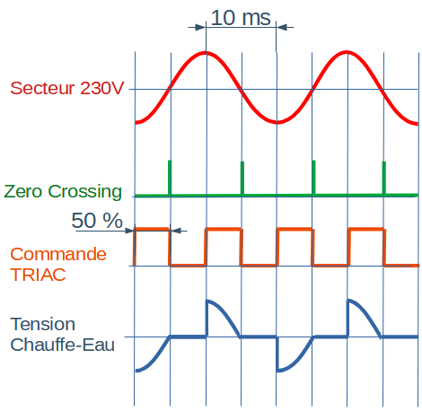
The “Zero Crossing” signal is used to synchronize the micro-controller to open the Triac between 0 and 100% of the time of a half-period of 10 ms depending on the level of energy to be transferred to the water heater.
Measurement
Measuring the 2 values representing voltage and current takes about 150uS. In practice, it is planned over a period of 20ms (1/50Hz) to sample 100 pairs of values, which will give a good description of the a priori sinusoidal voltage and of the current often disrupted by switching power supplies.
To properly time each measurement, the “Zero Crossing” signal from the dimmer is used. It changes to 1 for 500 µs every 10 ms when the 230v voltage is zero.
Every 40ms, we do:
- measurement of voltages and currents for 20ms
- an average of the last measurements to smooth and reduce measurement noise
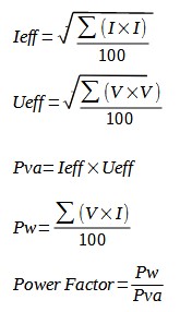
- the calculation of the effective current Ieff (RMS)
- the calculation of the effective voltage Ueff (RMS)
- the calculation of the apparent power Pva in kVA
- the calculation of the active power Pw in kW
- the cosine φ
A prior calibration must be made to define the multiplicative constant kV in the program which allows the conversion of the voltage measured in binary to the real voltage. Likewise for the current, the constant kI . Use a voltmeter, ammeter clamp or your grid counter for calibration.
The convention adopted is to have Pw positive if current fromGRID is consumed and Pw negative in the event of overproduction. If the sign is reversed, turn the current probe half a turn on the mains phase or reverse the wires.
Calibration
A prior calibration must be made to define the multiplicative constant kV in the program which allows the conversion of the voltage measured in binary to the real voltage. Likewise for the current, the constant kI . Use a voltmeter, ammeter clamp or your Electricity meter for calibration.
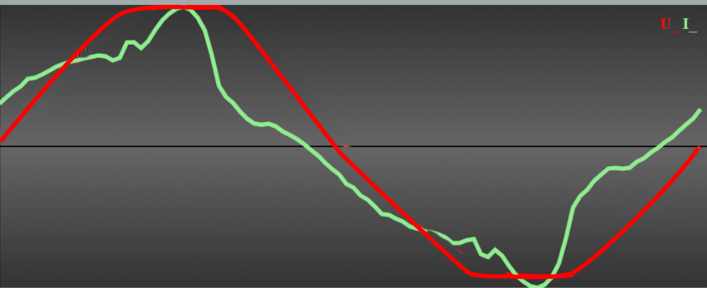
Depending on the transformer used for voltage measurement, there may be adjustments to be made. If the red voltage curve is a nice sinusoid, don’t change R4 and R5. If the curve is flat at the top or bottom, raise R4 or lower R5.
Then, start by measuring with a voltmeter the exact voltage of the sector. For example, if the value displayed by the assembly is 10% below your measurement, increase the kV value by 10%. For the current, if you do not have an ammeter clamp, use the electricity meter which displays the apparent power of VA or W. Compare with the value given by the system and increase or decrease the value of kI accordingly.
The convention adopted is to have Pw positive if current from electricity provider is consumed and Pw negative in the event of overproduction. If the sign is reversed, turn the current probe half a turn on the mains phase or reverse the wires.
Total Harmonic Distortion
At the request of developers of version 1 of the system, I added the “Total Harmonic Distortion rate”. THD.
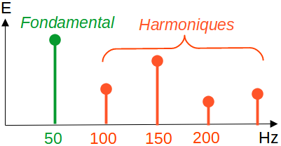
An ideal voltage and current are defined by a perfect sinusoidal shape at 50 Hz. In practice, devices (switching type power supplies or others) introduce non-sinusoidal currents generating numerous harmonics at 100 Hz, 150 Hz, 200 Hz, 250 Hz and disturb the operation of generators, transformers, etc. The THD will measure the energy contained in the harmonics (Total Energy – Energy of the signal at 50 Hz) in relation to the main energy and give a percentage.
0% = a perfect sine wave at 50 Hz,
100% = all the energy is in the harmonics
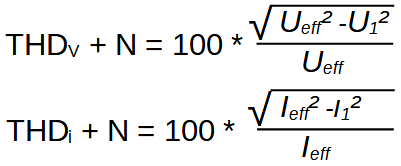
Here, for simplicity of calculation, the result includes the noise energy N in addition to the harmonics.
Operation
Every 40 ms, the voltage and the current are measured on 100 points for 20 ms. If the active power Pw is directed towards the public network (Pw<0), the triac opens a little more to favor the transfer towards the water heater. This is repeated until the equilibrium point is reached where Pw is close to zero.
If the temperature is reached, the water heater thermostat cuts the power supply to the resistance. In this case, the router will open the triac to the maximum, but no overproduction will be consumed. The Pw value will become strongly negative, from the level of overproduction. From a certain value, you can activate (optional) a relay to consume on another device. We stop it if the overproduction stops. Be careful to have a difference between the on and off threshold greater than the consumption of the device so as not to have an oscillation input of the relay.
At night, if the tank’s heating level is not reached, the grid Day/Night relay is left to take over (if it is retained) or the router can be programmed to open the Triac. The router takes the time on the internet network. Be careful, in the event of an internet cut, it may become out of sync. Put an activation time slot that covers winter and summer time to avoid time adjustments.
In the source code, you will find reporting to the Domoticz system. This is an example, as an option, to send data outwards if needed.
For the sake of simplicity, I have limited the functionalities to the essentials. People comfortable in programming can add other Triacs or relays. Similarly, it is possible to add a 20A current probe to measure and display the current sent to the water heater.
Web Page
The code installed on the ESP32 includes a Web server that displays on one page the various measurements as well as the voltage and current curves during a period of 20 ms. Simply enter the ESP32’s IP address into the address field of your web browser.
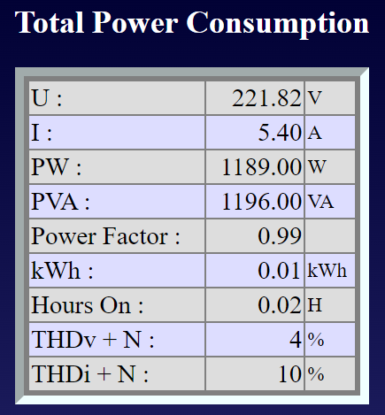
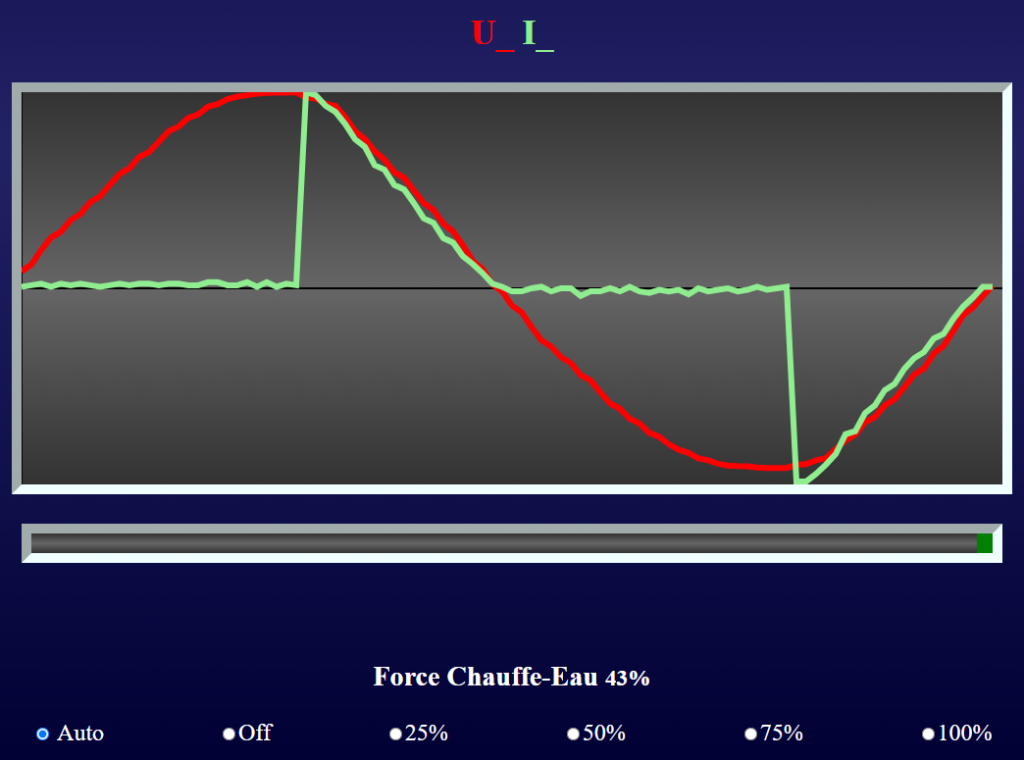
In “Auto” mode, the system adjusts the injection to the water heater in order to no longer send overproduction to the outside world. Other injection levels can be forced manually.
Assembly
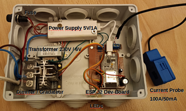
In an electrician’s box we install:
- The ESP32 card (Development Board 2*19 pins))
- A 5V 1A power supply for the ESP32
- A low voltage transformer to measure the voltage
- A 16A or 24A dimmer from RobotDyn
- Some resistors and capacitors for analog measurement circuits
- On the front 2 LEDs
Connected to this box, we have the current probe to be placed around the phase wire of the sector to be measured. Ground the shield to avoid picking up electrical noise.
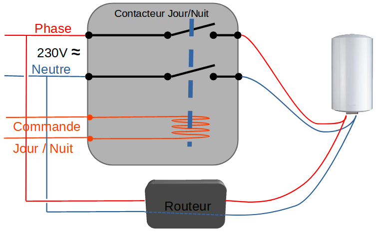
In the diagram below, we keep the Day/Night contactor and we install the router in parallel.
Note: the router does not switch the neutral but the phase/load only.
Source Code
All code is written using the Arduino IDE. It is initially injected by the serial link, then once in place, it can be modified if necessary by WIFI as described here https://f1atb.fr/programming-the-esp32-over-wifi/
The source code is composed of 3 files:
- the main file : SolarRouter_v2.ino
- the PageWebb.cpp file which contains the HTML and Javascript code of the web page
- the declaration file PageWeb.h
The source code is available here :
Check that you have the libraries installed like RemoteDebug on your Arduino IDE.
IP Settings
It is necessary to modify the first lines of the code in order to give the ESP32 the characteristics of your ethernet network at home.
/WIFI
const char* ssid = "nom_du_reseau_wifi"; //Put here your WIFI SSID
const char* password = "12345678"; //Put here the WIFI password
// Set your Static IP address
IPAddress local_IP(192, 168, 0, 208);
// Set your Gateway IP address
IPAddress gateway(192, 168, 0, 254);
IPAddress subnet(255, 255, 255, 0);
IPAddress primaryDNS(8, 8, 8, 8);    //optional
IPAddress secondaryDNS(8, 8, 4, 4);  //optional
On the first line, put the name of your Wifi network to which the ESP32 will have to connect.
In the second line, put the password of your Wifi network.
You must then give an IP address (IPAddress local_IP) to your ESP32 (it’s like a phone number). In general, internet boxes have a dynamic address field (which can change at any time) that they assign when someone connects to WIFI. If it’s your smartphone, great, you’re not trying to communicate with it. For the ESP, it must be assigned a fixed address. By going to your box to the network / DHCP section, you will find the field of dynamic addresses. For example, some boxes often assign dynamic DHCP addresses between 192.168.1.10 and 192.168.1.150. You then have a free field left to assign your own addresses between 192.168.1.151 and 192.168.1.253. Often the .254 and .255 are reserved for something else. You can thus give the address 192.168.1.200 to the ESP32 if no other machine on the network already occupies this address.
IPAddress gateway corresponds to the IP address of your box. It makes the bridge (gateway) with the outside world. Often, it is usually 192.168.1.1. The first three digits 192.168.1 must be the same for the box and your ESP. This is what is translated by the subnet mask (255,255,255,0) which says that the first 3 digits are fixed on the network and the last can change from machine to machine.
All these addresses are in IPV4 format, an old format which is very practical but which saturates and is being replaced by IPV6. If you have a PC under windows, type cmd in the search engine at the bottom, then in the black background page you type ipconfig . You will know a little more about your network and the IP address of your PC.
The primaryDNS and secondaryDNS correspond to the “Domain Name Server” which means the directory servers. When you type an address http://ToTo.com, these servers convert the name into an IP address, which only machines can understand. So your ESP when it has to look for the time at “fr.pool.ntp.org”, it can find a server. Don’t change them.
Soft Bugs
Please note, if you are unable to communicate between your PC and the ESP32, you are missing the driver for the USB interface. In general, it is the CP2102 which is on the ESP32 board. Many tutorials on the internet explain how to install it. Example: https://techexplorations.com/guides/esp32/begin/cp21xxx/
The Arduino IDE will ask you for a password when compiling. Answer anything, 1 letter minimum.
Sometimes with the Arduino IDE at the end of the transfer, the icon remains yellow and you no longer have control. Close the IDE and relaunch it.
On some configurations, during compilation, there is a non-existent library error: …..include <hwcrypto/sha.h>
With a text editor, open the file in your Arduino libraries C:\Users\User\Documents\Arduino\libraries\RemoteDebug\src\utility\Websockets.cpp
On line 42, replace:
include <hwcrypto/sha.h>
by
include <esp32/sha.h>
Don’t ask me why, on my desktop PC, I don’t need to make this change, on my laptop PC I need to.
Functional diagram
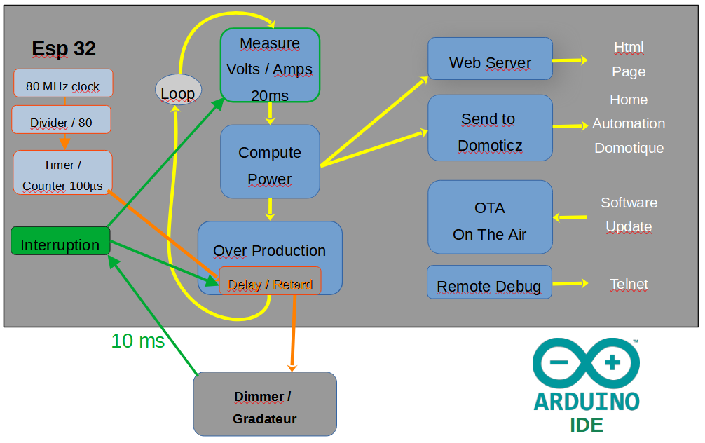
The dimmer with the Zero Crossing signal every 10ms, allows synchronizing the whole by activating an interruption on the ESP32. A timer provides an internal interruption every 100μs allowing the generation of a delay of 0 to 10ms in steps of 100μs to trigger the opening of the triac at the instant defined by the software.
Every 40ms and for 20ms, 100 voltage values and 100 current values are sampled and stored. Then the power calculations are made and can be sent to the web client that requests them.
Shower time

Now that you have hopefully understood how it works, you will notice that you have to take your shower in the morning on sunny days in order to take advantage of the overproduction at noon.
Security
By working on this 230V project, you agree to assume responsibility for your own safety and take all the necessary precautions to avoid electric accidents.
Articles sur le photovoltaïque
This Post Has 17 Comments
Comments are closed.
Hello,
I want to use your diagram and code for my water boiler but when loading the code with arduino IDE, I get an error for pageweb. Could you please tell me how to handle the Pageweb.h and cpp because I have no experience with C++.
Salutations,
Peter van Bergen
Peter
You must tell me more on the error to understand.
In the mean time, I did all the operations :
– uploaded the SolarRouter_v2.01.zip file from my website
– unziped the file
– clicked on the SolarRouter.ino file
– Arduino IDE was launched
– I did the compilation by clicking on the V symbol top left
– everything was OK
Regards
André
Don’t bother anymore. I’ve got it working. It was a hwcrypto issue.
It would be nice if you could add a solution to monitor this in Home Assistant.
Hello. Thank you for sharing this project. I built it on an pcb and did the first test today. When i increase the load, the Triac board sends the maximum of power to the load and keeps it on. Do you have any idea what can be the reason for this behaviour. The load is a 500 Watt/230V. resistor? I used a variable transformer to simulate the power injected to the grid.
Do you have set the current coil sensor correctly. Maybe you to turn it by 180°.
When you are in over production, you must see the phase of the current opposite to the voltage.
Bonjour André je rencontre se problème lors du téléversement , après les galères des librairies je débute
merci par avance
73 51 Bruno
In file included from C:\Users\yanni\AppData\Local\Temp\arduino\sketches\EDD44CE3E0EFD049DF0433B57C996B6A\sketch\SolarRouter_v2.01.ino.cpp:1:0:
C:\Users\yanni\AppData\Local\Arduino15\packages\esp32\hardware\esp32\2.0.9\cores\esp32/Arduino.h:194:12: error: ‘std::round’ has not been declared
using std::round;
^
exit status 1
Compilation error: exit status 1
A la lecture du message d’erreur, je ne comprends pas d’où cela vient. Je pense à un problème de bibliothèque. Si vous n’y arrivez pas, contactez-moi en privée f1atb.fr@gmail.com, je prendrai contrôle de votre PC à distance pour investiguer.
Cdlt
merci beaucoup je m’en occupe dans la semaine
Cdlt
Bruno
Hello André,
Thank you for sharing this. I built your system and it works very well. Maybe I will design a custom PCB in the future.
Kind regards,
Rob
Rob
Thank you for your positive report.
In the coming weeks, I will publish an upgraded version (V3.00_sonde) with new features and hardware compatible with the current version V2.01
Regards
André
Good news. I’m looking forward to it! Although, the current version does exactly what I need. 🙂
Fine, in the coming week, I will publish an upgrade with the same hardware but some improvement on software, to add relays and distribute the measurements to other Triacs.
Regards
André
Bonjour André,
I am finding your solar overproduction circuit interesting (thank you for sharing) and I have ordered the required parts from Ali Exp to get started.
In the mean time, I thought I’d use a spare ESP32 I have to run your SolarRouter_V2.01 software.
The code compiles with no problems, however the ESP32 with the SolarRouter software resets every 10 seconds approximately.
I can see the ESP32 resetting through the serial monitor.
I suspect this is because I don’t have a wifi network connected to the ESP32. Does that sound right to you?
Thank you for your help.
Regards,
Carlos.
Carlos
Yes, you are right.
The system reset periodically when it’s impossible to access internet.
Within one month, I expect to publish a new software version. It will not change the hardware. It will offer new features and more simplicity to program the actions.
Regards
Thank you for the prompt reply.
I look forward to the new version.
Regards,
Carlos.
Hi,
I was wondering if I could omit the zero crossing triac module and just fit the optional solid state relay for a small bathroom heater, about 250W. I would also like to know whether to start building v2.01 or wait for v3 to be released.
Thanks in advance.
Version 3.03 already exists https://f1atb.fr/index.php/fr/2023/07/07/u-x-i-routeur-solaire-pour-gerer-la-surproduction-photovoltaique-diy/
It’s not yet fully translate in english
You need a zero crossing Triac.
A bathroom heater of 250w seems very low power.
Regards
André
F1ATB