Analog Brightness Sensor
The LM393, purchased from AliExpress, is a brightness sensor that can be connected to nano computers such as the Orange PI. It has a digital output providing a 0 or a 1 depending on the brightness and the threshold adjustable by a variable resistor. Here we will be interested in the analog output which provides a voltage between 0 and 3.3v (for a 3.3v power supply) depending on the level of brightness. In strong light we are close to 0v, in weak light close to 3.3v.
The difficulty with the Orange Pi like other nano computers, it does not have an analog input to measure a voltage but only digital inputs. We will convert the analog voltage measurement into a capacitor charging time measurement starting from 0v until the digital input goes to 1.
Connection
Connect the LM393 to the + 3.3v of the orange pi zero and for example the resistance and capacitance assembly on the pin 11 or PA15 pin as shown in the diagram.
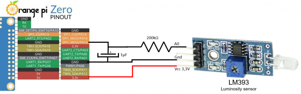
In this diagram, the pull up resistor is missing at input PA15/11 of orange pi by a few tens of kΩ. It makes a bridge with the 200kΩ which even if A0 is at 0V, the input level is seen as a 1.
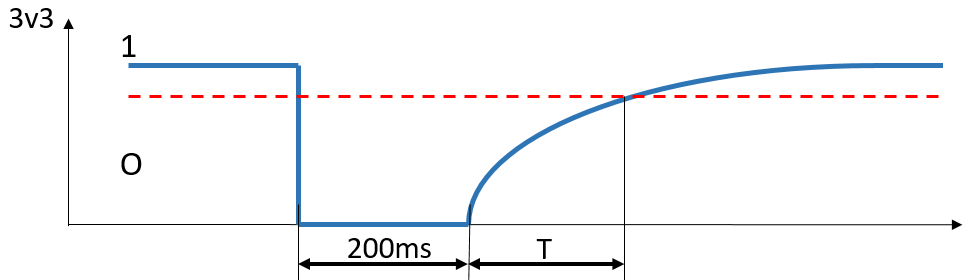
First, the PA15/11 pin is set to zero for 200ms to empty the 1µF capacitor. Then the PA15/11 pin goes into input, the capacitor is charged with the pull up resistor and the 200kΩ resistor which is connected to the A0 output of the light sensor. By measuring the loading time T in ms, we have a value representing the level of illumination.
Code
For the installation of the Armbian system, see the following article:
https://f1atb.fr/index.php/2020/08/06/getting-started-orange-pi-zero/
First for python 3, you have to update and add the pip installer. Then add the OrangePi.GPIO access library.
apt-get update
apt-get upgrade
apt install python3-pip
pip3 install OrangePi.GPIO
This library, OrangePi.GPIO, is described here https://pypi.org/project/OrangePi.GPIO/
It comes from the library adapted to the Raspberry Pi and well documented
https://opi-gpio.readthedocs.io/en/latest/api-documentation.html
In the event of an installation error, some additional libraries may be necessary.
apt install python3-dev
pip3 install setuptools
or
apt install python-dev
pip install setuptools
In root access, create the source test.py with nano.
nano test.py
import time
import math
import OPi.GPIO as GPIO

GPIO.setboard(GPIO.ZERO)
GPIO.setmode(GPIO.BOARD)  #refer as pin number
GPIO.setwarnings(False)

anal_in_out = 19 # pin 19 or PA15


Offset=70

while True:
    GPIO.setup(anal_in_out, GPIO.OUT)
    GPIO.output(anal_in_out, 0)
    time.sleep(0.2)
    GPIO.setup(anal_in_out, GPIO.IN,pull_up_down = GPIO.PUD_UP )
    T0=time.time() * 1000                  # temps en ms
    T=T0
    Tmonte=0

    while T-T0<400:                        # Timeout
        state = GPIO.input(anal_in_out)
        T=time.time() * 1000
        if state==1:
            Tmonte=T-T0
            T=T0+400


    Lumi=math.floor(Tmonte-Offset)
    print ("Lumi",Lumi)

    time.sleep(1)
Test the set with:
python3 test.py
Notes
- To discharge the capacitor, we can reduce the time to 10ms, that is enough.
- The offset allows to zero the response when 3.3v is input. As the voltage drops, the times increase, but in a non-linear fashion. This does not constitute a precision analog digital converter but already gives a good idea.
- With a resistance bridge at the input, we can adapt to a greater dynamic of voltages. But be careful never to exceed 3.3v to avoid damaging the Orange Pi.
- To avoid a program waiting loop, we can do a rising edge detection