GPSDO = GPS Disciplined Oscillator
This acronym denotes a quartz oscillator whose frequency is measured using a very precise clock based on GPS signals and which generates one or more clocks at the output of phase locked loops (PLL). This method makes it possible to optimize the qualities of precision and stability of the clocks.
With a ‘simple‘ quartz one can obtain a precision of 1 x 10 -6 or 10Hz for 10 Mhz or 10 Khz for 10 Ghz, but subject to slow drift depending on the temperature and its aging. This is an insufficient level of precision for a transceiver working in SSB in the microwave bands.
The system proposed here provides 2 clocks whose frequency is programmable between 25kHz and 200 MHz. They can be used for example to control an LNB (Low Noise Block converter) of a parabolic antenna and a transmitter / receiver in order to guarantee a perfect frequency setting. The precisions we can expect are of the order of 3 * 10 -8.
The assembly can be controlled remotely with a simple web browser in order to be able to locate it at the foot of the antennas.
Principle of operation
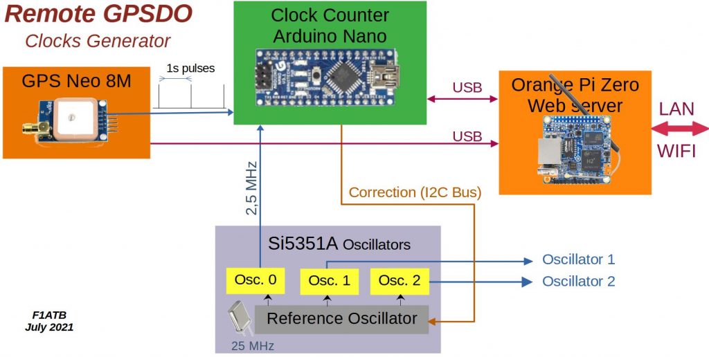
A GPS provides us with a very precise time base with a pulse every second. A counter will count a clock from the reference quartz at 2.5 MHz for 40 s. The measurement of the number of clock pulses, in theory 100 Million, after 40s will allow us to correct the frequency of the reference quartz to set the clock exactly at 2.5 MHz. Two other clocks, synchronous with the first, provide the signals to drive our LNB or transceiver.
Hardware
GPS
The Neo 8M GPS is an inexpensive model (5 € at Aliexpress) which provides a clock pulse every second and location data on the serial bus or via the micro USB port in NMEA format. For more details see the article:
https://f1atb.fr/diy-your-gps-tracker/
In fact, it is more correct to speak of GNSS (Global Navigation Satellite System) and not GPS, because this receiver deals with the 4 positioning systems or satellite constellations:
- the original US historical GPS
- Galileo developed by Europe
- Glonass developed by Russia
- Beidou developed by China
A red LED flashes in seconds once the satellites have been acquired. It may take a while the first time.
Si5351A
The Si5351A is a generator of 3 clocks up to 200 MHz synchronous with a 25 MHz crystal, the frequency of which can be corrected if it drifts slowly.
The Si5351 is programmed to output a 2.5 MHz signal on the CLK0 output pin. This pin is connected to pin D5 of an Arduino Nano which is the input of an internal 16 bit counter with an overflow register.
The other 2 clocks have the frequency and the level programmable by the I2C bus connected to the Arduino. We can go up to 200 MHz.
For information, we find the Si5351A circuit in the HackRF SDR treated in other posts.
The module with the output connectors is available from Aliexpress for less than 10 €.
Arduino Nano
The Arduino Nano, well known to amateurs of programmed objects, has very interesting counting functions. Here, it counts the number N of 2.5 MHz periods received during 40s based on the one second clock of the GPS connected to D2.
If the count result differs from the 108 = 40 * 2.5 * 106 expected. The Arduino program calculates a new calibration factor or correction of the 25 MHz reference frequency and sends it to the Si5351 through an I2C bus.
Orange PI Zero
To control the assembly and monitor it remotely, we use an Orange PI Zero single board computer under Armbian which runs an Apache Web server. A Raspberry Pi 3 can do the trick, but an Orange PI Zero with ethernet, wifi, also does it for a weaker QSJ. It communicates with the Arduino and the GPS by USB, which requires a mini-hub to have 2 USB ports.
The Orange PI is important on restart by providing the Arduino and the Si5351A with the last known correction in order to launch the oscillators as close as possible to the correct frequency even in the absence of acquisition of the satellites.
The board with 512MB of memory is available from Aliexpress for around twenty €.
Wiring
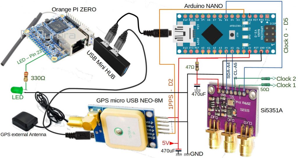
The whole is powered by 5V, 3A max. Thoroughly filter the general power supply to generate clean clock signals. As the Si5351A can be powered between 3.3v and 5v, a 47 ohm resistor followed by a 470uF capacitor filters its power supply.
The I2C Bus to drive the clock module connects to the Arduino:
- SDA – A4
- SCL – A5
The Clk0 is sent to pin D5 of the Arduino. The other 2 clocks are available directly on the SMA connectors or pins. Here a resistance of 50 ohm limits the max current. The output must be adapted according to the desired use. At no load the outputs provide a 0 to 3.3v square wave signal.
The GPS provides the 1pps signal (1 pulse per second) to be connected to D2 of the Arduino. An antenna is located directly on the board. If it is hidden to acquire satellites, an external active antenna can be connected.
An LED on pin 23 via a 330 ohm resistor lights up if the Orange PI has started and flashes if the satellites are acquired.
Construction
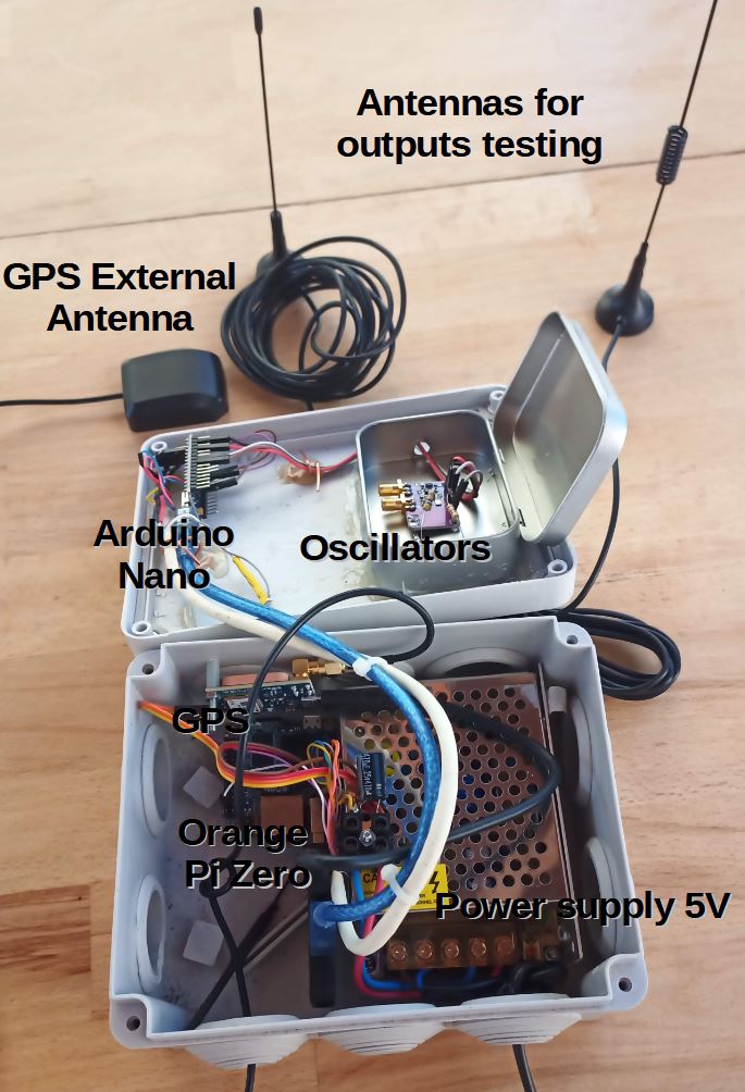
The whole is mounted in an electrician’s box. The oscillators are in a metal box with 2 SMA plugs on the surface for the clock outputs.
Softwares
The Arduino Nano runs the software for counting the pulses and calculating the correction to be applied to the reference quartz at 25 MHz.
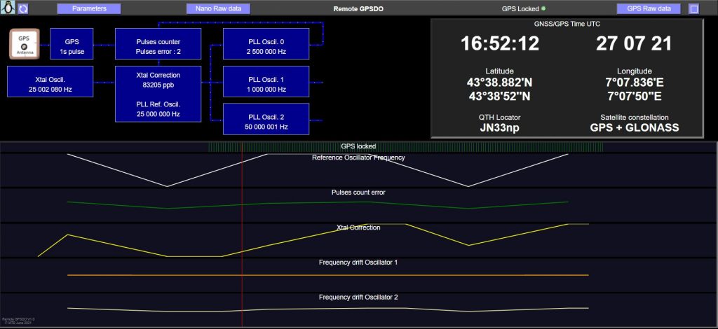
On the Orange Pi, a Python application collects information from the Arduino and GPS. During a web client call to the system’s IP address, the history of satellite acquisitions is returned as well as the frequencies of the 2 clocks. All the files are to be put in the / var / www / html folder corresponding to the basic configuration of an Apache web server.
The software in Beta version which allow the use of the GPSDO presented can be downloaded here. There is one folder for the Arduino and one for the Orange Pi Zero.
GPSDO_F1ATB_Sources_V1_Beta_2021_08
Performance test
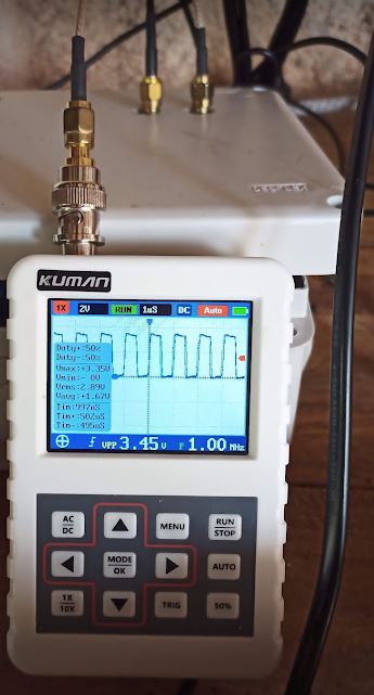
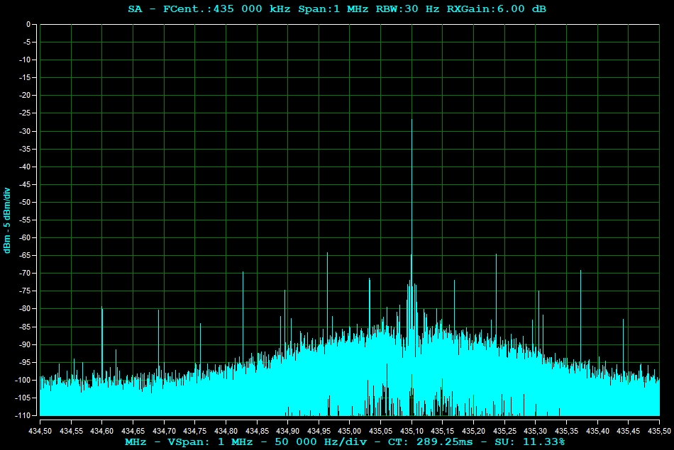
For the GPSDOs it is interesting to test the frequency stability and the spectral purity. For this, I performed a test in use condition, by connecting the GPSDO to the external clock of a HackRF transmitting on 435.1 MHz.
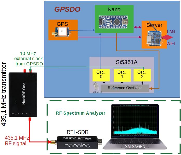
A simple spectrum analyzer based on an RTL-SDR key and SATAGEN software on a PC makes it possible to observe the quality of the signal generated.
For frequency stability, great. The deviations measured every 40s by the Arduino do not exceed 5 pulses out of a total of 100 Million. The Orange Pi’s web interface gives the curve in real time.
On the spectrum side, the result is unfortunately not very good. Spurious lines appear at -40 dB / -50dB under the main line at 432.1 MHz. If you use the HackRF’s internal oscillator or an internal TCXO, this phenomenon does not appear.
The position of the lines depends on the correction coefficient applied to the reference PLL of the Si5351 circuit.
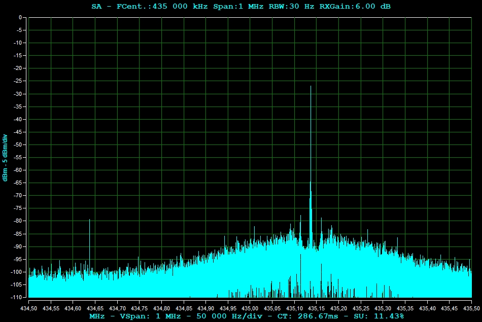
With the design given here around an SI5351 circuit, we get an acceptable result to generate a low power beacon but not a high power transmitter. My conclusion is:
INSUFFICIENT RESULTS
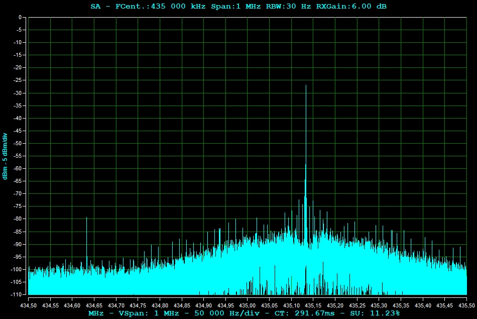
Spectrum at GPSDO output
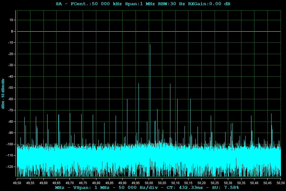
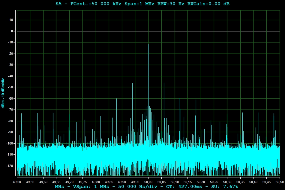
Below are 2 spectra around 50MHz of the oscillator output without and with compensation for the drift of the SI5351 quartz. In both cases, large lines depending on the compensation coefficient.
If you have any ideas to improve. I’ll take it.
F1ATB
André
Hi, can I have your email address because I still have a few questions
I’m making a printout for Remote GPSDO
73,PA0HAH
I will publish in the coming weeks the software of my GPSDO. I am currently testing it.
andre.buhart(@)gmail.com
73
André
The sources can be downloaded now. I will not detail it as I will reduce for the moment my efforts on the subject as the results are not as expected.
Great work. The design looks good.
Hello André,
excellent work, I like the idea of a remote GPSO very much!
It’s nice to the support a ADALM Pluto and a LNB with decent clocking signals and manage everything remotely. Is the relevant code integrated in the latest RemoteSDR environment or is there something to do in order to integrate things manually? Would be nice to know what to do because running two native webservers (Apache vs. NodeJS) on a single Pi may cause some conflicts ;-()
73 es tnx fer yr work!
Karl-Heinz, DC4PC
RemoteSDR is a transceiver based on SDR operating on Ham radio bands. You can control it remotely from anywhere.
Remote GPSDO is a totally different system, it’s a GPS you can also control remotely, running on a separated platform. The issue I have with Remote GPSDO is that the spectra of the signal generated is not good enough. So I stopped the development as mentioned at the end of the post.
73 André