QO-100 Receiver
Remote SDR – Receiver module
Below the presentation of a SSB receiver based on SDR (Software Defined Radio) remotely controllable by an internet browser as found on the web, the famous WebSDR.
HarDware
For the hardware, the set presented here includes:
- an SDR like RTL-SDR or HackRF One
- a nanocomputer like the Orange Pi PC2 H5 or the Orange PI One Plus with ARMBIAN. Note that OMs like CU2ED ran the RX from Remote SDR on a Raspberry 4 (23% load).
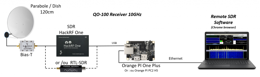
For SDR, the “HackRF One” model is interesting because it covers a wide band from 1 MHz to 6 GHZ. It allows listening to 2.4 GHz broadcast during a transmission to Q0-100. It is available in China (Aliexpress) for a hundred € with its aluminum box and a TCXO for frequency stability.
The RTL-SDR, more limited in frequency, makes it possible to work on 6m up to the 740MHz output from the LNB of the satellite dish receiving the QO-100 satellite. It has the advantage of its low cost.
The 2 SDR models are limited to an 8-bit dynamic range. This is sufficient for QO-100 as the levels of each transmission are very similar. This is also acceptable for 2m or 70cm unless there is a nearby relay which can saturate the input.
The nano processor is a model from the Orange PI family. It looks like the Raspberry PI. I tested the proposed treatment with an Orange PI PC2 H5 and an Orange PI One Plus H6. It is the latter that I use daily, it is found for less than 30€ in China (Ebay or Aliexpress). These 2 processors are 4 cores 64-bits. They are loaded at 60% with the reception chain proposed below. A Raspberry PI3 does not hold the load, as for the Raspberry PI 4, I have not tried.
Software
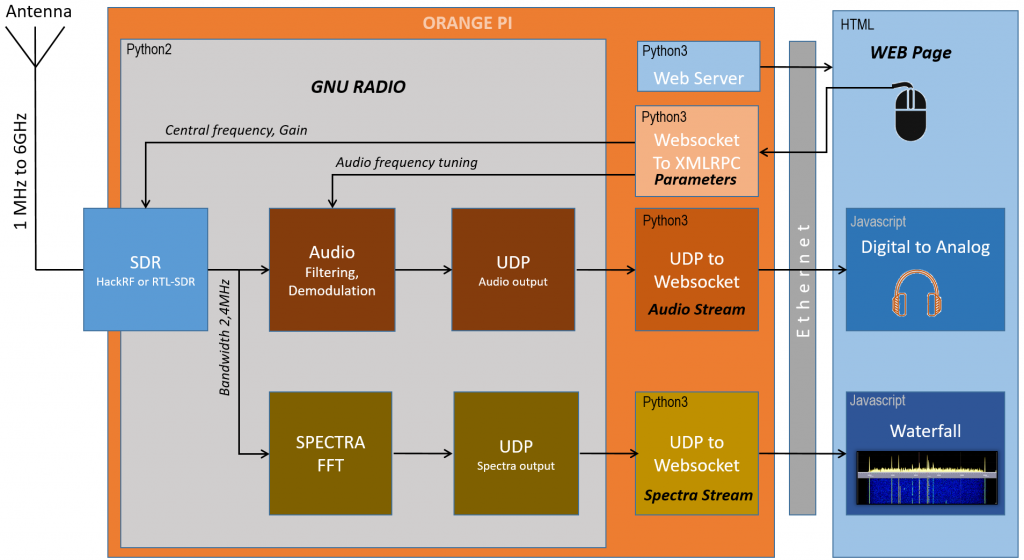
On the software side we have:
- signal processing with GNU-Radio in python2
- a simple web server in python3
- 3 small modules in python3 interface between GNU-Radio and websockets for exchanging data with the web browser of the PC or remote tablet
- The “Remote SDR” audio, visualization and processing software written in HTML and Javascript to control the unit remotely from a web browser like Chrome.
Signal Processing
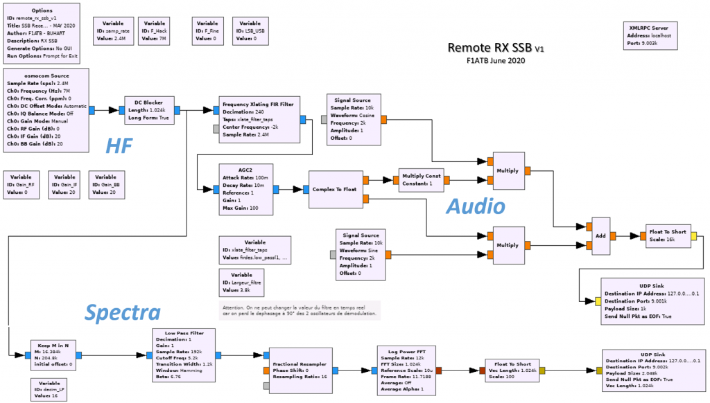
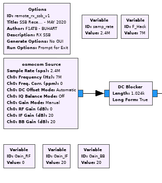
All of the processing is carried out using “GNU Radio” software. It has a graphical editor “Gnuradio-companion” which facilitates the task because it provides all the processing blocks to make a receiver without writing a line of code. It’s almost a breeze … The source file of the processing graph is available on Github F1ATB / Remote-SDR.
HF PROCESSING
For the RF input part, the SDR is processed by the Osmocom block which will provide it with parameters such as the center frequency, the gains and the desired sampling frequency. In the case of HackRF, you can choose a central frequency between 1MHz and 6GHz. For the sampling frequency it is necessary to work between 2MHz and 10MHz maximum. It will give the bandwidth processed. A HackRF can work below 2 MHz but this is to be avoided because there is aliasing.
For an RTL-SDR, the theoretical sampling frequency range is:
- 225001-300000 Hz
- et 900001-3200000 Hz
In practice, you should not exceed 2.4 MHz because above the PLL does not sometimes synchronize.
In the case of a receiver dedicated only to the reception of the narrowband transponder of QO-100, a useful band of 500 kHz and therefore a sampling at 600 kHz is sufficient. This makes it possible to reduce the computing load of the Orange Pi or even to use a Raspberry PI3B. However, a 600 kHz sampling is too low for a HackRF and not covered by the RTL-SDR.
The choice made here is 2.4MHz. This allows:
- to work with a HackRF or RTL-SDR
- to have a useful working band of 2 MHz after filtering which is well suited to 2M band
- to have by decimation the useful bands of 1MHz, 500KHz, 250KHz and 125KHz
a useful band of 500KHz well suited to QO-100
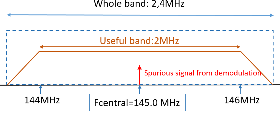
The SDR provides 2 complex I and Q signals at demodulation output sampled at 2.4MHz. This principle of demodulation due to the disparities between the I and Q channels in the digital analog conversion generates in the center of the band a spurious signal peak. The HackRF has a function to compensate for this bias. However, we added a block called “DC blocker” in GNU Radio to remove this component. It is difficult to say which of the two systems is more effective, the bias varying over time. In all cases, these high-pass filtering functions disturb reception around the center frequency.
AUDIO PROCESSING
The audio processing chain is used to connect a channel to a web client. It is not planned to have several headphones in parallel on different channels. Since SSB audio signals are less than 4 kHz, the sampling frequency chosen for the web client is 10 kHz so as not to overload the output bit rate.
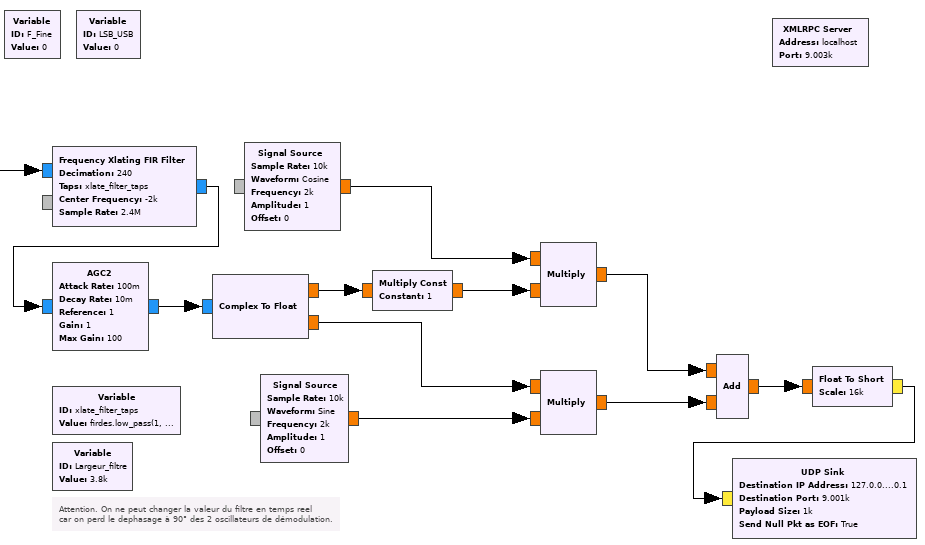
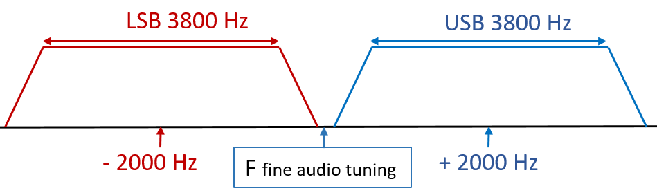
In the 2 MHz (from -1 MHz to + 1 MHz) of the useful band at the output of the SDR, the operator chooses a listening frequency called here fine frequency. The audio channel is filtered in a band from 100Hz to 3900Hz. The filtering is not carried out by a 100 to 3900Hz bandpass filter but by a complex low-pass filter of + -19ooHz. This filter of + -1900Hz wide is positioned at the fine frequency – 2000 Hz if we are in lower sideband (BLI or LSB) or fine frequency + 2000 Hz if we are in upper sideband (BLS or USB). This allows listening in an audio band from 100 Hz to 3900 Hz. The band is a bit wide for SSB but can be refiltered later by the web client. This maximum width to cover all cases is necessary because it is impossible to change the demodulation frequency of the 2 quadrature oscillators (sine and cosine) in real time. Tests have shown that you lose perfect quadrature if you change the frequency.
At the output of the filter, there is a decimation by 240 which allows the sampling frequency to be lowered to 10 kHz = 2.4 MHz / 240. Then an AGC block crops the dynamics of the complex audio signal (blue signals). A block then makes it possible to separate the real part and the imaginary part in two (orange signals). One signal is sent for multiplication by a cosine at 2 kHz, the other to a quadrature sine at 2 kHz also. The choice LSB or USB is defined by the variable LSB_USB which acts on one of the channels by multiplying the signal by 1 or -1.
The adder recovers the demodulated channel and transmits the data in floating numbers to a 16 bit integer converter with a cropping of the dynamics which on 16 bits will be quite sufficient for SSB audio.
GNU Radio outputs audio frames in 1000-byte packets using the UDP protocol on port 9001 of Orange PI. To send these packets to the web client, we use a web socket on port 8001 of Orange PI. A small python3 module discribed here,takes care of the transfer from port 9001 UDP to 8001 websocket and the web client.
SPECTRAL PROCESSING
To have a display of the entire spectrum over the SDR sampling width (2.4 MHz), we perform a fast Fourier transform (FFT) of 2048 points. This provides about 2 MHz useful given the filtering at the edges. A decimation by 2, 4, 8 or 16 makes it possible to have a zoom up to 125 kHz of useful band or 150 kHz of sampling. For 2048 points of FFT the resolution is 150 kHz / 2048, or about 75Hz.
To understand the processing chain, we have to start from the end and what meets our needs. Namely, a frequency of 5 traces of spectrum per second is sufficient to have a direct view of the activity on the band. It is absolutely not necessary to perform an FFT on all the time samples (2.4 M / s) provided by the SDR.
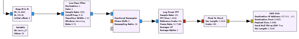
By taking 12000 samples per second = 2.4MHz / 200 this meets the need. GNU Radio has a block that performs 2024 point FFT and calculates energy directly in logarithmic level to get dB. The output being packets of 2048 points in floating number, one carries out a conversion into integers 16 bits then a sending by UDP on the local port 9002. As for audio a small module in python 3 converts these UDP messages in websocket for the web client on port 8002.
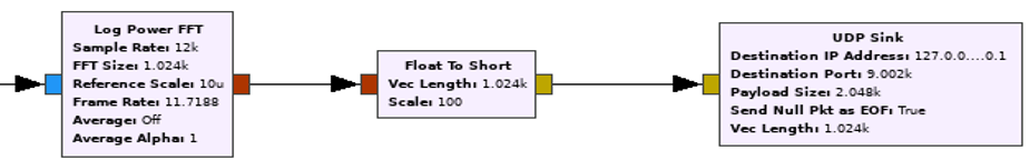
This FFT must be fed with packets of2048 time samples. 5.8 = 12000/2048 packets are needed per second if you want an FFT that covers 2.4 MHz of band. If you want a band 16 times smaller by 150 kHz you need 16 times more samples as input to a filter which is centered on a band 16 times smaller followed by a decimation by 16. Phew …, a little difficult to follow …
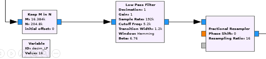
GNU Radio has a block which allows you to choose M samples from N. In the case of a 150 kHz band, we take 32758 = 2048 * 16 samples from 409600 that we filter low-pass in a ratio of 16 . At the input of the filter we are at 192k = 16 * 12k sampling frequency. At the output there is a decimation by 16 to arrive at 12k from the entrance to the FFT. Decimation is not done directly in the filter block because it cannot be changed in real time to work on other bandwidths such as 300, 600 kHz etc.
RECEIPT OF ORDERS
To control SDR and signal processing in GNU Radio you must receive a certain number of parameters from the remote web client. The connection is made by a websocket on port 8003 of Orange PI. Again a small module in Python3 discribed here, converts websocket messages to an XMLRPC interface on port 9003 which allows to pass them to GNU Radio.
REMOTE VIEWING AND DRIVING
As already mentioned the control of the whole is done remotely in a web page (Chrome) provided by the mini web server in python3 on the Orange Pi and port 8000 (Remote SDR V1 only).
http://Orange_PI_address:8000/remote_sdr.html
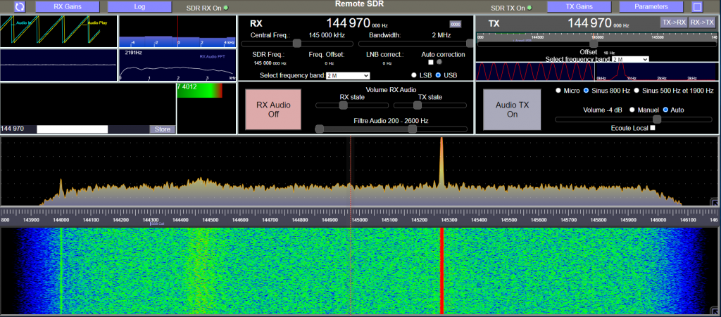
This part in HTML and Javascript called “Remote SDR” will be the subject of another article.
REMOTE TRANSCEIVER
This receiver is part of a complete remote controllable transceiver as presented in these posts:
Note that the source code and image for an Orange Pi One Plus are available on Github: https://github.com/F1ATB/Remote-SDR
Olivier
I have published now all the posts adressing the subject of Remote SDR on my website.
The main page in english is here: https://f1atb.fr/index.php/2020/07/21/remote-sdr-2/
The main page in french is here: https://f1atb.fr/index.php/fr/2020/07/21/remote-sdr-distant/
The source code is also available on GitHub: https://github.com/F1ATB/Remote-SDR
Don’t hesitate to contact me if you need some explanations.
Regards
André F1ATB
https://f1atb.fr
Fernando
I have published now all the posts adressing the subject of Remote SDR on my website.
The main page is here: https://f1atb.fr/index.php/2020/07/21/remote-sdr-2/
The source code is also available on GitHub: https://github.com/F1ATB/Remote-SDR
Don’t hesitate to contact me if you need some explanations.
Regards
André F1ATB
https://f1atb.fr
Hi Andre,
Thanks for making the project available.
I’m currently trying to use 2 HackRF with a single computer running Debian and everything is almost up and running. Whenever I click on either the refresh button, I get the following error message:
node:events:491
throw er; // Unhandled ‘error’ event
^
Error: connect ECONNREFUSED ::1:8002
at TCPConnectWrap.afterConnect [as oncomplete] (node:net:1481:16)
Emitted ‘error’ event on Socket instance at:
at emitErrorNT (node:internal/streams/destroy:151:8)
at emitErrorCloseNT (node:internal/streams/destroy:116:3)
at process.processTicksAndRejections (node:internal/process/task_queues:82:21) {
errno: -111,
code: ‘ECONNREFUSED’,
syscall: ‘connect’,
address: ‘::1’,
port: 8002
}
Node.js v18.13.0
This seems to be that the streaming server is not running. but shouldn’t it when Radio_Server.js is launched?
Can you please assist.
Thank you.
It’s difficult to answer as your configuration is not similar to my configuration with Armbian on Orange Pi or Raspberry Pi OS.
Regards