ESP32-2432S028 ESP32-2432S024 JC2432W328
ESP32 Wroom with Screen and GPIO Extension
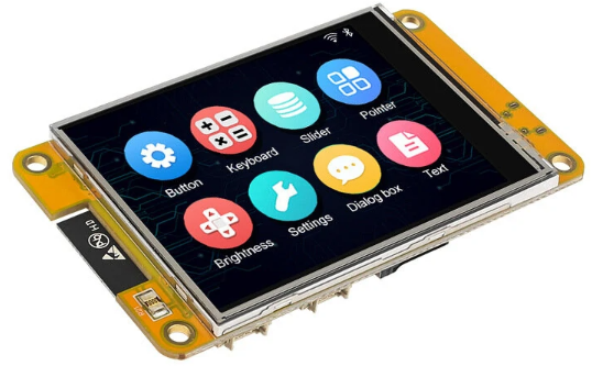
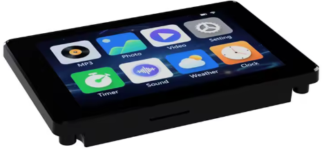
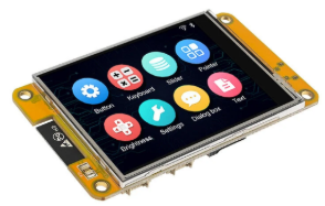
For those who want to build a project using the ESP32 and an integrated 320×240 pixel screen, there is a range of very interesting boards available. They come with either a resistive or capacitive touchscreen.
- Resistive touch panel
- ESP32-2432S028R
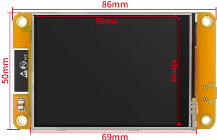
- Display2.8′
- Display type ILI9341
- Back Light gpio 27
- ESP32-2432S028
- Display 2.8′
- Display type ST7789
- Back Light gpio 27
- ESP32-2432S024
- Display 2.4”
- Display type ILI9341
- Back Light gpio 21
- ESP32-024
- Display 2.4′
- Display type ST7789
- Back Light gpio 21
- ESP32-2432S028R
- Capacitive touch panel
- ESP32-2432S024
- Display 2.4′
- Display type ILI9341
- Back Light gpio 21
- JC2432W328
- Display 2.8′
- Display type ST7789
- Back Light gpio 27
- ESP32-2432S024
Each board includes:
- an ESP32 Wroom (dual-core)
- 320*240 pixel touchscreen
- an ambient light sensor
- a 3-color LED on the front or back (red: GPIO 4, green and blue: GPIO 16 or 17 depending on the board)
- an XPT2046 resistive touch sensor or a CST820 capacitive touch sensor
These boards are also called “ESP32-Cheap-Yellow-Display” or CYD and can be found on Aliexpress..
These boards do, however, have a weakness for certain applications: the limited number of GPIO pins. Only 3 are available in the basic version, and up to 6 in the JC2432W328 version.
Display
Several libraries exist for use with the Arduino IDE. Personally, I used “LovyanGFX”. See the example below, which is compatible with the 6 models shown.
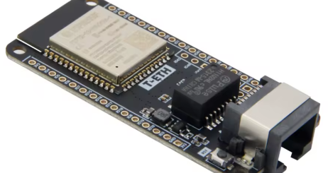
ESP32 Wroom
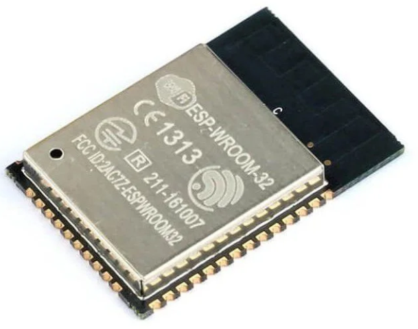
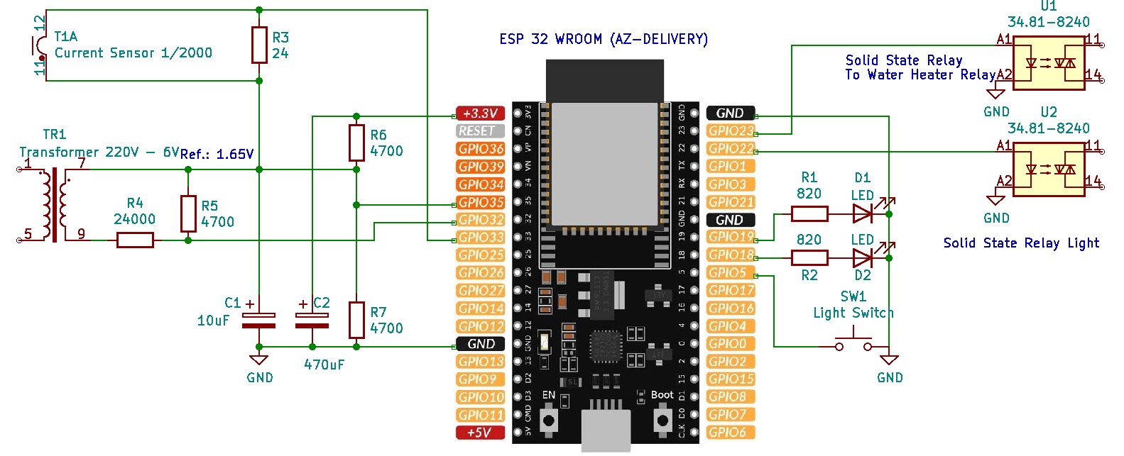
The ESP32 Wroom is a dual-core processor running at 240MHz with built-in Wi-Fi and Bluetooth, enabling powerful applications such as the F1ATB photovoltaic router.
With the Arduino IDE, you need to configure the “Espressif” board manager (Espressif develops the ESP32) in the preferences. Go to File / Preferences and enter the address: https://dl.espressif.com/dl/package_esp32_index.json

ESP32-2432S028R
This 2.8-inch card is available in two configurations with an ILI9341 type screen or an ST7789 screen and a resistive touchscreen.
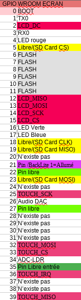
GPIO
It only has 3 GPIO pins available (here in green): 22, 27 and 35. Unfortunately, 35 only works as an input, digital or analog.
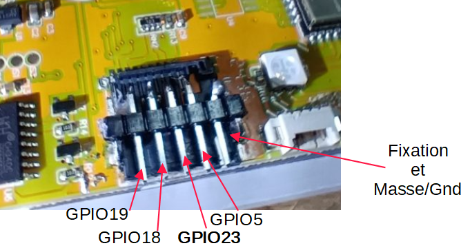
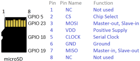
To expand the number of GPIO pins, you can easily repurpose those used for the micro-SD memory card if you’re not using it (shown in yellow in the table). You can use a “Card-Sniffer,” available on AliExpress. It’s a dummy memory card that provides the GPIO pins.
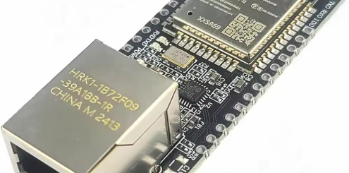
The metal casing of the bracket can also be desoldered to access the four GPIO pins used to control the SD card. Then, 2.54mm pitch Dupont pins can be soldered, attaching the assembly to the solder points on the casing on the sides.
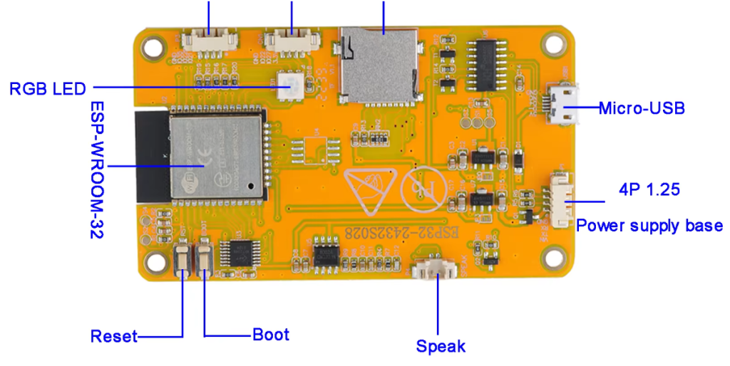


The connectors on the board are 4-pin 1.25mm JST connectors.
LDR Ambient Brightness
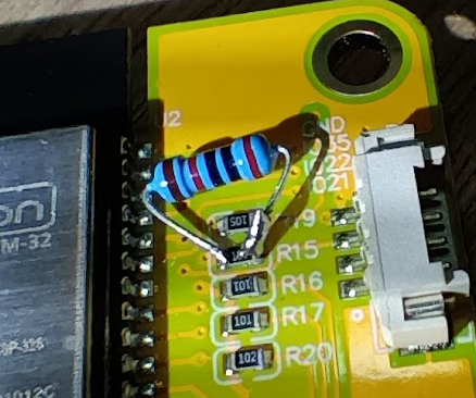
On the front of the board, there’s a variable resistor that adjusts with brightness. Its supply resistance is too high. It needs to be reduced to achieve good analog measurement dynamics on GPIO 34. Solder a 20 to 47k ohm resistor in parallel with R15. This way, by measuring the voltage on GPIO 34, you can integrate a brightness measurement into your program.
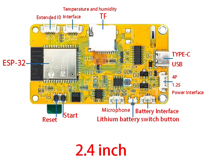
ESP32-2432S024
This family of 2.4-inch cards features either a resistive or capacitive touchscreen (capacitive is preferable). The screen is either an ILI9341 or ST7789.
For the GPIO pins, only 3 are available: 21, 22, and 35. Note that pin 35 is only an input pin. As in the previous example, we can retrieve the GPIO pins that control the micro-SD connector.
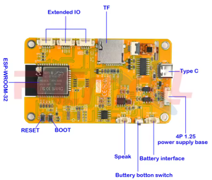
JC2432W328
This is the most interesting board with a 2.8-inch screen, a capacitive touchscreen (more practical than resistive), and 6 available GPIO pins. However:
GPIO 4: Turns on the red LED with a 0. Best used as an output.
GPIO 16: Turns on the green LED with a 0. Best used as an output.
GPIO 17: Turns on the blue LED with a 0. Best used as an output.
GPIO 21: As an input or output.
GPIO 22: As an input or output.
GPIO 35: As a digital or analog input.
Power Supply

It is possible to power the board via the micro-USB port or via the 4-pin connector next to it with a power supply that provides 5V and 700mA minimum.
WARNING: With these boards, a screen that’s fully powered on and Wi-Fi enabled can draw significant current. If the power supply can’t keep up, the ESP32 will malfunction and leave you confused..
Speaker
On GPIO26, there is a small amplifier allowing you to connect a small 4 or 8 ohm speaker, in order to send audio signals if needed.
Code sample
Attached is a code example for the cards:
- ESP32-2432S028,
- ESP32-024,
- ESP32-2432S028
- ESP32-2432S024
- ESP32-2432S024
- JC2432W328
Install the LovyanGFX library in the Arduino IDE. A Google search will provide the instruction set for controlling the graphics generator.
Unzip the file and compile it in the Arduino IDE.
The code is also available on Github
Using the 115000 baud serial port, if you send H or ?, you will receive a summary of the commands for selecting the card model and display rotation. For devices with a resistive touchscreen, touching the screen will initiate a calibration phase.
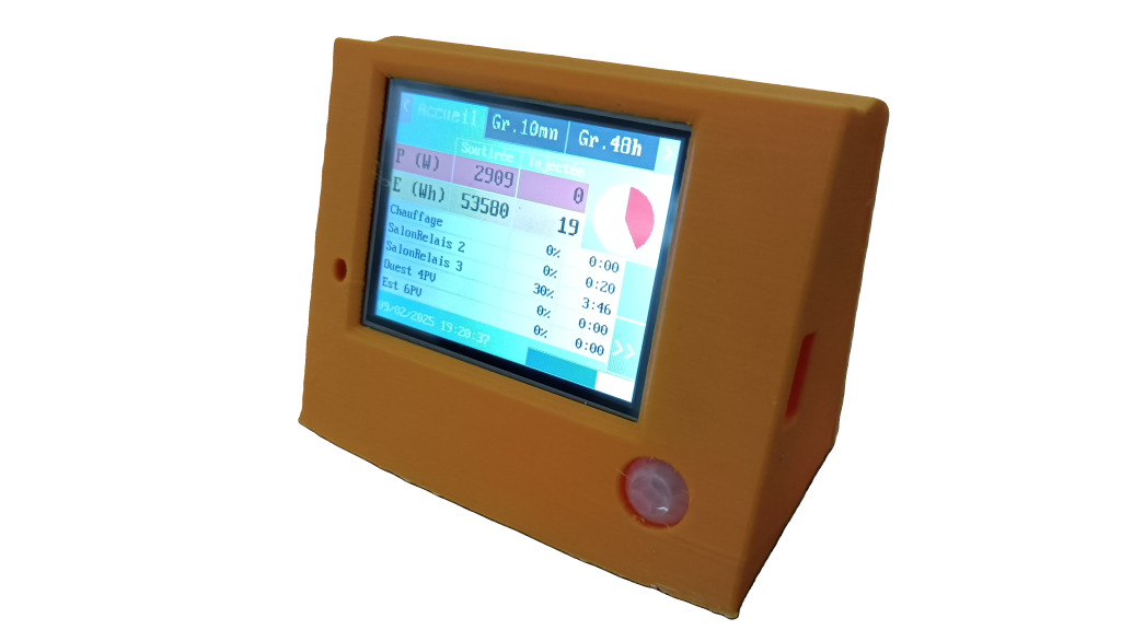
Assembly
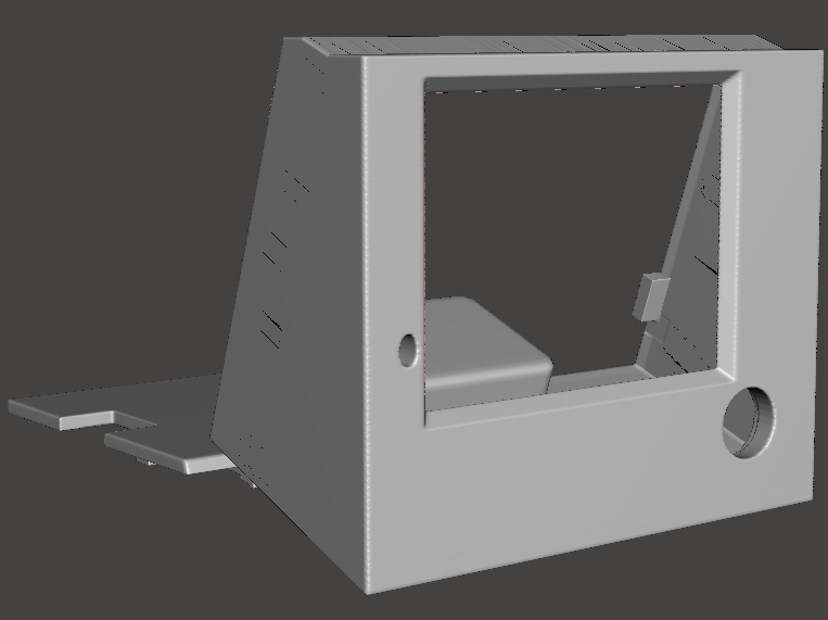
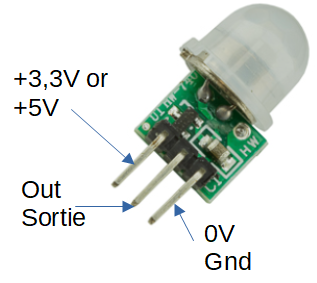
For mounting the 2.8-inch screens, I suggest a 3D-printable box that includes the back cover. The hole in the bottom right corner allows you to house a PIR sensor (GPIO 35, for example) which, through programming, can turn on the screen if someone approaches it. The lower section can accommodate the 230V/5V 700mA power supply described earlier.
Video Presentation
/


Recent Comments