Architecture
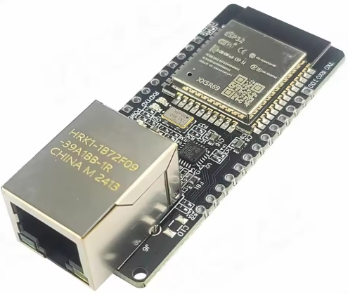
The ESP32 is a high-performance microcomputer with a dual-core processor, digital and analog interfaces, and Bluetooth and Wi-Fi communication capabilities. Some boards also include an RJ45 connector for direct Ethernet connectivity.
Configurations
There are 2 versions of boards on the market:
- ESP32-ETH01 :
- chip version : ESP32-DOWB-V3
- revision : 301
- WiFi
- Ethernet
- WT32-ETH01 :
- version du chip : ESP32-DOWB
- revision : 101
- WiFi crashes
- Ethernet
I have a preference for the ESP32-ETH01 board, it works in Ethernet and Wifi. The WT32-ETH01 board, works in Ethernet but I was not able to communicate in WiFi.
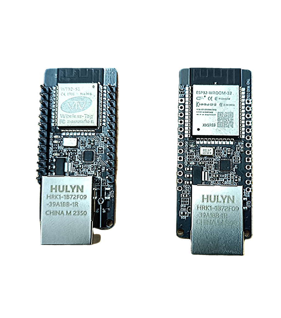
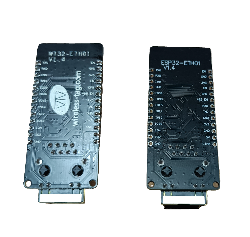
The WT32-ETH01 board, left, has a slightly smaller ESP32 enclosure than the ESP32-ETH01 board
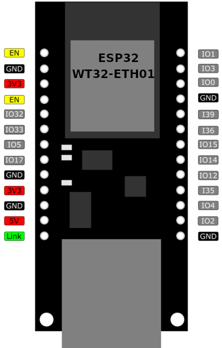
Wiring
Wiring the system with an Ethernet card is similar to many other setups with the 38-pin ESP32 WiFi card.
There are a few constraints to consider when assigning the GPIOs:
- GPIO 0: Do not use. Set to 0 before powering up to enter board programming mode. Otherwise, leave it set to 1 during normal board operation.
- GPIO 1 or TX0: TX pin of serial port 0 for communication.
- GPIO 2: Digital and analog I/O (Input/Output). This pin must be set to 0 when programming the board. Preferably use only as an output.
- GPIO 3 or RX0: RX pin of serial port 0 for communication
- GPIO 4: Digital I/O and Analog I/O
- GPIO 5: Digital I/O, but sends a PWM signal during boot
- GPIO 12: Digital I/O. Must be set to zero during boot
- GPIO 14: Digital I/O and Analog I/O, but sends a PWM signal during boot
- GPIO 15: Digital I/O and Analog I/O, but sends the boot log on TX0 if set to 1
- GPIO 17: Digital I/O
- GPIO 32: Digital I/O and Analog I/O
- GPIO 33: Digital I/O and Analog I/O
- GPIO 36: Digital I and Analog I
- GPIO 39: Digital I and Analog I
- EN: Set to 0 briefly and then released, it resets the Card
- 3V3: Powers the card with 3.3 volts or can supply 3.3V if the card is powered with 5V.
- 5V: +5V power input
- GND: Ground and negative of the power supply
- LINK: Indicates whether an Ethernet cable is connected or not.
Be careful, GPIOs provide output signals between 0 and +3.3V. As inputs, they only accept signals between 0 and +3.3V. NEVER apply 5V to a GPIO input. This is not like Arduino boards.
Software download
The Arduino IDE development tool allows you to write and compile the software. In the IDE preferences, you must use the “Espressif” board manager, which develops the ESP32. Go to File / Preferences and enter the address: https://dl.espressif.com/dl/package_esp32_index.json
Boards with RJ45 connector do not have USB connector for programming. You need to connect an FTDI232 board. The TX on the FTDI side goes to the RX of the ESP32 and the RX on the FTDI side goes to the TX of the ESP32. Set the FTDI jumper to 3.3V. Connect the grounds (Gnd). Connect the 3.3V if your ESP32 board is not powered directly.
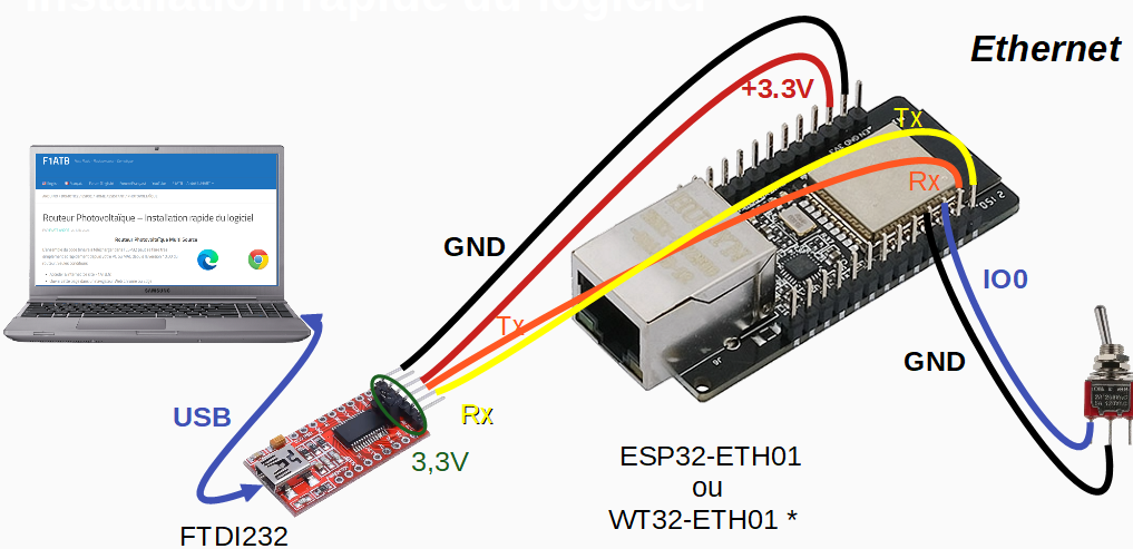
To download the program code, you need to ground GPIO0 (Gnd) and then apply power. You can then remove the ground on GPIO0. Then, ask the Arduino IDE to compile the source code and download the object code.
If you notice untimely reboots of the ESP32, you probably have the 3.3V power supply via the FTDI232 card which is not sufficient. Disconnect the 3.3V power wire between the FTDI232 and the card. Put a 5V power supply between ground and the 5V input of the ESP32 card. Leave the jumper on 3.3V of the FTDI232 card so that it continues the dialogue in 3.3V with the TX and RX pins.
Example of a home automation application
To familiarize yourself with this card, I offer you a small application with different functions useful for home automation.
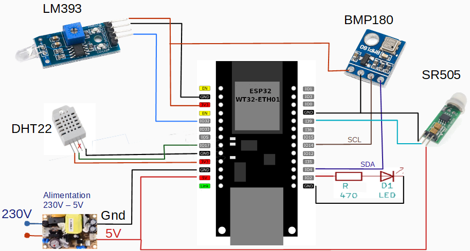
Temperature and Humidity Measurement
We use a DHT22 sensor connected to GPIO17, ground, and +3.3V. There is no pullup resistor between +3.3V and the Data output as in some schematics. This works with the ESP32’s pullup.
For the software, you need the “DHT.h” library.
Atmospheric Pressure Measurement
A BMP180 sensor provides atmospheric pressure and the temperature around the board. It connects using the I2C bus. The default GPIOs, 21 and 22, cannot be used. Instead, we use 4 and 14. For the software, we use the “Adafruit_BMP085.h” library, which is compatible with the BMP180.
Light Measurement
An LM393 light sensor provides an analog voltage between 0 and 3.3V depending on the light captured by the sensor. The value is read directly in analog form on the GPIO32 input.
Motion Detector
An SR505 infrared sensor (GPIO39) detects human or animal movement. Note: to function properly, it must operate at 5V. The output signal only rises to 3.3V for a few seconds when detected.
Proper Operation LED
An LED on GPIO2, behind a 330 ohm to 1000 ohm resistor, flashes every 2 seconds to indicate that the ESP32 is working.
Watchdog
For the software component, a watchdog continuously monitors the Ethernet connection, testing access to a remote server (yours, Google, or…). After 3 minutes of no response, the ESP32 resets.
Sleep
Although the ESP32’s power consumption is low, given its minimal work monitoring the various sensors, it is put to sleep for only 1 second every second to avoid delaying the Ethernet connection.
Web Server
A web server is installed to access the various measurements from a PC or smartphone.
Every 10 minutes, a report is sent to a remote server with a simple GET request like this: http://distant_server.com/My_report.php?server=Example2025&temp_piece=22.2&humidite=55….mme de l’ESP32,
The ESP32 dates the measurements by fetching the time from the internet.
Over-the-Air (OTA) Update
After an initial software installation using the FTDI board, it is possible to update the software via Ethernet using the ArduinoOTA library.
Source Software
In the zip file below, you will find the full source code. If one of the sensors is missing (DHT22 or BMP180), hide the corresponding code to avoid crashing the software.
Construction of a Photovoltaic Router
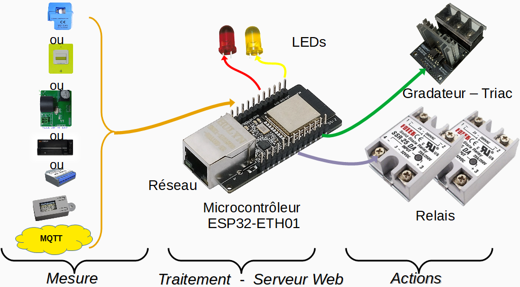
Another example of construction: a photovoltaic router.
Power Supply Selection
Generally, a 5V 1A power supply is sufficient. If your ESP32 doesn’t boot properly, it may be because the power supply isn’t able to provide the current pulse required for a clean reset to initiate the boot procedure. In this case, replace the power supply.
POE Power Supply
To power the module, you can supply 5V or 3.3V to the appropriate pin. An alternative is to power it via the Ethernet cable using the POE (Power Over Ethernet) method.
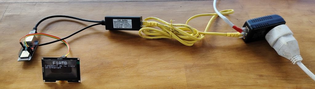
48V is sent over the Ethernet cable, via a 230V / 48V power supply. A splitter separates the Ethernet signal and the power supply by providing 5V.
Shopping list
- ESP32-ETH01
- FTDI232
- Fils Dupont Female/Female
- Power Supply 230v – 5V ou 3.3V 700mA
- DHT22
- BMP180
- LM393
- Module LED + resistance
Option POE (Power Over Ethernet)