GPIO on Orange PI One Plus H6
The Orange PI One plus is one of the many Orange Pi boards offering interesting features:
- processor ARM H6 Quad-Core 64 bits
- ethernet 1GB
- USB 2
- HDMI
- OS: ARMBIAN .
- price <30€ including power supply -available at Aliexpress
To access the GPIO of an Orange PI, you can use one of the libraries like OPI.Gpio. In the case of the Orange Pi One Plus, the python program head must make the following declarations:
import orangepi.oneplus
from OPi import GPIO
This library uses the Sysfs virtual filesystem introduced by the Linux kernel which allows system commands to activate GPIO pins. In the following lines we will deal with these commands without using the OPI.GPIO library.
While the Sysfs virtual file method is simple and adapts to all cards, it does not allow the input resistance to be set in PULLUP or PULLDOWN. In addition, the actions sometimes take ms which makes it impossible to check for a few micro seconds.
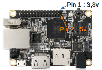
Connector Orange Py One Plus board
The One Plus board has a 26-pin connector according to the diagram below.
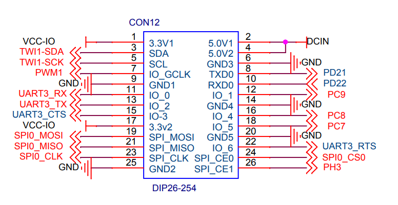
To address one of the input or output pins, you must find the reference of the corresponding GPIO. The table below is valid for the Orange Pi One Plus H6. So if you want to use pin 26, it corresponds to GPIO 227.
| 1 | 3.3V | 2 | 5V |
| 3 | TWI1-SDA / PH6 / GPIO230 | 4 | 5V |
| 5 | TWI1-SCK / PH5 / GPIO229 | 6 | GND |
| 7 | PWM1 / PH4 / GPIO228 | 8 | UART2-RTS / PD21 / GPIO117 |
| 9 | GND | 10 | UART2-CTS / PD22 / GPIO118 |
| 11 | UART3-RX / PD24 / GPIO120 | 12 | SDC2-D3 / PC9 / GPIO73 |
| 13 | UART3-TX / PD23 / GPIO119 | 14 | GND |
| 15 | UART3-CTS / PD26 / GPIO122 | 16 | SDC2-D2 / PC8 / GPIO72 |
| 17 | 3.3V | 18 | SPI0-WP / PC7 / GPIO71 |
| 19 | SPI0-MOSI/ PC2 / GPIO66 | 20 | GND |
| 21 | SPI0-MISO / PC3 / GPIO67 | 22 | UART3-RTS / PD25 / GPIO121 |
| 23 | SPI0-CLK / PC0 / GPIO64 | 24 | SPI0-CS / PC5 / GPIO69 |
| 25 | GND | 26 | SPI1-CS / PH3 / GPIO227 |
Example Oscillator on pin 26
Below a program in python 3. Attention, important constraint. You must be root to access the GPIO.
#!/usr/bin/python3  Python 3 environment
#-- coding: utf-8 --
import os              # To execute system command
from time import sleep # this lets us have a time delay
numgpio=227
numgpio=str(numgpio)
print ("numgpio:"+numgpio)
os.system("sudo echo "+numgpio+" > /sys/class/gpio/export")
os.system("sudo echo out > /sys/class/gpio/gpio"+numgpio+"/direction")

try:
         print ("Square signal around 50Hz . Press CTRL+C to exit")
         while True:
              os.system("echo 0 > /sys/class/gpio/gpio"+numgpio+"/value")
              sleep(0.01)
              os.system("echo 1 > /sys/class/gpio/gpio"+numgpio+"/value")
              sleep(0.01)


except KeyboardInterrupt:
         # set port/pin value to 0/LOW/False
         os.system("echo 0 > /sys/class/gpio/gpio"+numgpio+"/value")
         # Clean GPIO
         os.system("sudo echo "+numgpio+" > /sys/class/gpio/unexport")
         print ("Bye from F1ATB.")
to launch it, if the program is on your desktop:
python3 /home/utilisateur/Desktop/Nom_du_programme.py
Orders can be entered by hand from a terminal window.
The … export command activates GPIO 227 which corresponds to pin 26.
The direction command, here out to be output.
The commands value alternately at 0 or 1 to make an oscillator.
Then in case of Ctrl-C, we finish cleanly by freeing the GPIO 227.
To get rid of the root issue, a solution can be to launch the program when starting the Orange PI which in this case is in root before going into user mode. Just modify the /etc/rc.local file (sudo nano /etc/rc.local). Put the launch command with the path in absolute (python. /Home/……py) before exit 0 of the rc.local file.
Posts on Remote-SDR
- Remote SDR V5 -Raspberry 4B or Orange Pi Image Installation
- Remote SDR v5 – Manual Installation
- Remote SDR v5
- QO-100 Satellite Live
- RTTY
- Troubleshooting
- QO-100 Transceiver
- SSTV
- WSJT-X – FT8
- Omnirig – Remote SDR
- Communication Ports
- Tone generators
- Setting of GPIO outputs
- Band Scanning
- Gains and Dynamics
- Frequencies Management
- Launch of Remote SDR
- CPU Cooling
- Web GUI
- Microphone and signal processing authorization
- Configurations
- Characteristics
- Introduction to Remote SDR
- Remote SDR – Audio Channels
- CW with Remote SDR
- Rotary Knob and Morse Manipulator for Remote SDR
- VHF and UHF NBFM Transceiver
- Remote SDR v4
- Gpredict — Remote SDR
- Remote SDR V4 – Raspberry Pi 4B or Orange Pi Zero 2 image installation
- Remote SDR v4 – Manual Installation
- SA818 – RTL-SDR
- Remote SDR – Examples of realization
- Transmit over QO-100 satellite with a Smartphone
- Remote SDR V2 – Software Architecture
- Remote SDR V1- Purchase
- Remote SDR V1 – Man Machine Interface
- Remote SDR V1 – Signal Processing
- Web Client to GNU Radio
- GNU Radio to Web client
- Remote SSB Transmitter
- Remote SSB Receiver
- GPIO on Orange PI One Plus H6
- TCXO installation on HackRF
- Q0-100 Transceiver with 2 SDR – Remote SDR V1



Hello, thank you for this detailed explanation but unfortunately it doesn’t help me with my current problem.
I have also an OPIone+ and would like to implement this GPIO-Control with a relay(switch) in Octorint with the plugin “PSU Control” so that I will be able to switch the 3D printer on/off by software commands?
With the PSU-Control plugin it´s possible to adjust some parameters (GPIO pins Gcode commands) which I tried with no success.
Would be a pleasure if you could help me out here!
Are you in root? With GPIO you need to be in root or give the authorization to the user to access the GPIO.
Put a file in /etc/sudoers.d/
which contains:
user_name ALL=(ALL) NOPASSWD: /usr/bin/python3
if it’s a python3 application which access the GPIO
Regards
I tired it in PSU Control ( Switching -> System Command) with system functions like e.g. gpio write 117 1 and with echo 1 > gpio117/value (to switch the relay on) but did not work.
By doing it in Armbian with following commands it works with no problems:
root@orangepioneplus:~# cd /sys/class/gpio
root@orangepioneplus:/sys/class/gpio# ls
export gpiochip0 gpiochip352 unexport
root@orangepioneplus:/sys/class/gpio# echo 117 > export
root@orangepioneplus:/sys/class/gpio# ls gpio117
active_low device direction power subsystem uevent value
root@orangepioneplus:/sys/class/gpio# echo out > gpio117/direction
root@orangepioneplus:/sys/class/gpio# cat gpio117/direction
out
root@orangepioneplus:/sys/class/gpio# echo 1 > gpio117/value //ON
root@orangepioneplus:/sys/class/gpio# echo 0 > gpio117/value //OFF