Remote SDR V1 – Man Machine Interface
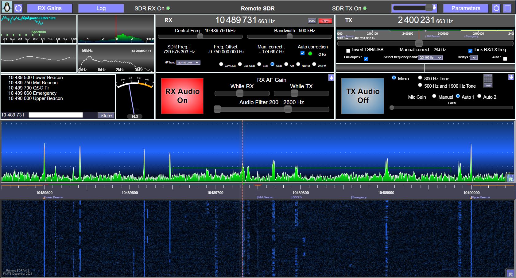
The “Remote SDR” Man Machine Interface (MMI or GUI) is grouped on a single web page. It allows simultaneous remote control of a receiver and a transmitter. The layout of the graphic elements adapts to all screen sizes. For the smallest like those of smartphones, some lower priority information is hidden. It also reduces the graphics processing power required. Since the definition is mainly done by style files (CSS), it is easy to modify the layouts of information and colors.

A click on the button at the top right of the page forces a more pleasant full screen presentation.
Reception frequency
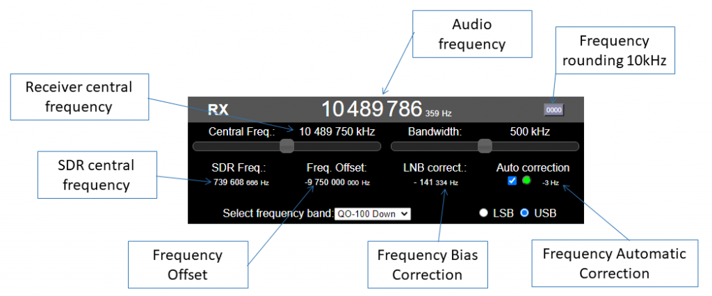
On this screen, the large central value indicates the reception frequency of the Audio channel. By placing the cursor on one of the numbers, it can be modified with the mouse wheel. The center frequency of the reception spectrum can be modified as well as the useful bandwidth between 125 kHz and 2 MHz. With the button “0000” it is possible to align directly to the nearest multiple of 10 kHz.
In the case for example of an LNB which lowers the receive frequency, the offset value and the working value of the SDR is displayed.
To compensate for any frequency offset, a correction can be introduced manually. By placing the cursor above the numbers, it is possible to modify them with the mouse wheel.
If beacons have been defined in the configuration file, it is possible to track them in frequency and to automatically apply a corrective every second to stay well established.
Audio channel in reception
An analysis of the audio channel on reception is proposed to provide a detailed report to the correspondent.
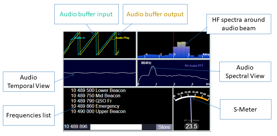
An input buffer for 10kHz audio samples allows them to be stored before the audio API faces 44kHz playback to the speaker. The blue-green sawtooth curve shows the loading index of this buffer which has a signal depth of 2.5s. A straight slope shows smooth data entry from Orange PI and the network. The yellow sawtooth shows the index playing by the audio API to the speaker. A straight slope shows a web browser that is not overloaded. Sometimes non-linearities show a PC busy with another task. The slight time difference between the 2 curves shows the margin there is to absorb the differences between writing and reading. Signal processing manages the interpolation to go from 10kHz to 44kHz and tries to keep the time margin as small as possible so as not to delay the audio signal too much.
A zoom of the HF channels around the audio channel is provided. It helps with frequency setting.
A temporal analysis (oscilloscope) allows the analysis of the audio signal.
A spectral analysis also allows a frequency analysis and provides the frequency of the maximum signal received. This helps to tune the frequency of the transmitter to the receiver when it sends a modulated carrier at 800Hz.
A table gives the frequencies recorded in the configuration file or stored in memory by the user. A click on it positions the audio channel there.
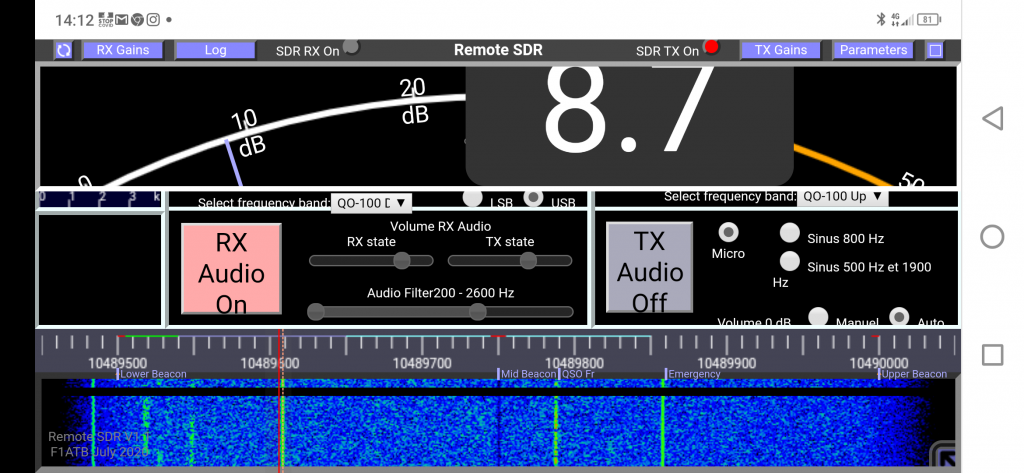
An S-meter gives the signal level above the noise of the lowest in the useful band processed by the SDR. A click on the S-meter displays it in full width. This is a useful feature for aligning an antenna with the reception level of a beacon shown in large size on a smartphone screen.
HF spectrum in reception

The spectrum in the processed HF band is represented in the form of amplitude as a function of the frequency and in the form of “waterfall”. Dotted lines define a scale in steps of 10dB. It is possible to modify the dynamics and the zero level of each of the representations to adjust it as well as possible.
The configurationRX.js file allows you to define certain characteristic frequencies to reach them with a click. Likewise along the frequency scale, it is possible to color areas. For example in red the forbidden bands, in green the bands reserved for SSB.
Two markers give the frequency in reception and in transmission. A click on the screen allows you to quickly reposition the reception marker. With the left mouse button you can also move the marker.
SDR gains in reception
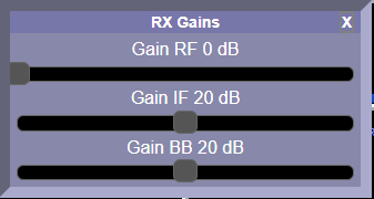
Depending on the SDR model chosen (RTL-SDR or Hack RF One) there are up to 3 gains to be set for the internal amplifiers. With a few tries we find the right settings.
Transmission frequency
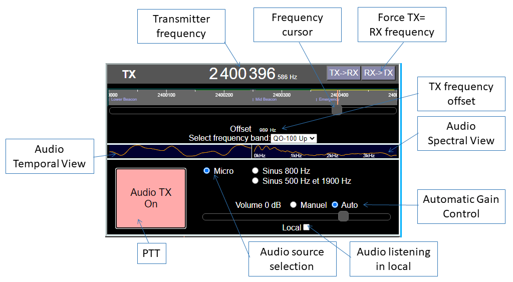
The central number gives the transmission frequency. This is adjusted with the cursor below or by rotating the mouse wheel above one of the numbers.
It is possible to enter a frequency offset to compensate for an error in the SDR crystal.
A temporal and spectral analysis of the audio signal makes it possible to control what is transmitted. You can listen to yourself locally to check your microphone.
The microphone gain should preferably remain on ‘Auto’ in order to have a clean transmission. In full manual, we can see on the waterfall that the transmission is not clean.
SDR gains in transmission
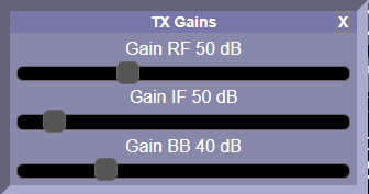
With the SDR Hack RF One there are 3 gains to be set for the internal amplifiers. With a few tries we find the right settings.
Connection status
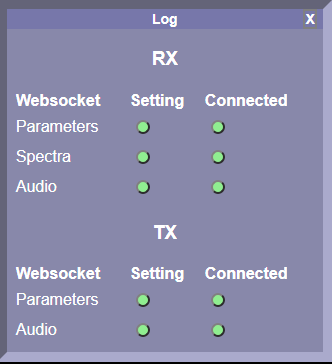
It is possible to check the state of the connections between Remote SDR and the 2 Orange PIs. The LEDs in the first column in green record that the connection request using the websocket protocol has been made. The second column indicates that the connection is successful.

The 2 SDR RX On and SDR TX LEDs, initially red, should go on and remain green after a few seconds.

In the event of a problem, the red indicator lights for example. A click on the button at the top left of the page relaunches the loading of all the files from the server.
IP settings
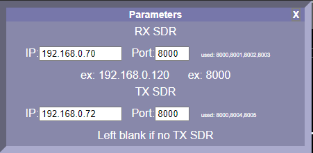
You must give the browser the IP addresses of the 2 Orange PIs on the local network as well as the ports, 8000 by default. The other ports of websockets 8001, 8002 etc will be deduced from this (see the pages on signal processing). A priori, we launch the remote_sdr.html web page from the Orange PI server of the receiver and port 8000.
http://IP_recepteur:8000/remote_sdr.html (Remote SDR V1 only)
Posts on Remote-SDR
- Remote SDR V5 -Raspberry 4B or Orange Pi Image Installation
- Remote SDR v5 – Manual Installation
- Remote SDR v5
- QO-100 Satellite Live
- RTTY
- Troubleshooting
- QO-100 Transceiver
- SSTV
- WSJT-X – FT8
- Omnirig – Remote SDR
- Communication Ports
- Tone generators
- Setting of GPIO outputs
- Band Scanning
- Gains and Dynamics
- Frequencies Management
- Launch of Remote SDR
- CPU Cooling
- Web GUI
- Microphone and signal processing authorization
- Configurations
- Characteristics
- Introduction to Remote SDR
- Remote SDR – Audio Channels
- CW with Remote SDR
- Rotary Knob and Morse Manipulator for Remote SDR
- VHF and UHF NBFM Transceiver
- Remote SDR v4
- Gpredict — Remote SDR
- Remote SDR V4 – Raspberry Pi 4B or Orange Pi Zero 2 image installation
- Remote SDR v4 – Manual Installation
- SA818 – RTL-SDR
- Remote SDR – Examples of realization
- Transmit over QO-100 satellite with a Smartphone
- Remote SDR V2 – Software Architecture
- Remote SDR V1- Purchase
- Remote SDR V1 – Man Machine Interface
- Remote SDR V1 – Signal Processing
- Web Client to GNU Radio
- GNU Radio to Web client
- Remote SSB Transmitter
- Remote SSB Receiver
- GPIO on Orange PI One Plus H6
- TCXO installation on HackRF
- Q0-100 Transceiver with 2 SDR – Remote SDR V1
Note that the source code and image for an Orange Pi One Plus are available on Github: https://github.com/F1ATB/Remote-SDR
